Ford Ecosport: Exterior Lighting / General Procedures - Headlamp Adjustment
Adjustment
-
NOTE: If the flash video link does not load or is incompatible with your browser, a .wmv version of the video can be accessed at: http://www.fordservicecontent.com/Ford_Content/videos/FusionHeadlampAdj2.wmv
Click on the link above to view video.
Click here to view a video version of this procedure.

All headlamp types
NOTE: Refer to the Owner's Literature for the headlamp adjustment screw location.
NOTE: Consult your state vehicle inspection manual for recommended tolerance ranges for visual aiming.
NOTE: Horizontal aim is not adjustable.
-
Identify the headlamp type. Vehicles are equipped
with Visually Optically Aligned Left (VOL) or Visually Optically Aligned
Right (VOR) headlamps. Molded in small letters on the headlamp lens is
one of the following: VOL and SAE or VOR and SAE.
-
NOTE: Before starting headlamp adjustment, entry conditions must be met.
-
Vehicle must be on level ground.
-
Tires must be correctly inflated.
-
Vehicle must be normally loaded.
-
Headlamps must be clean.
-
Headlamps must operate correctly.
-
Air suspension switch must be on (if equipped).
-
Vehicle must be on level ground.
-
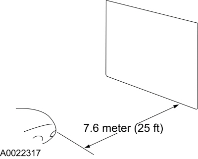
NOTE: The vertical wall or screen must be a minimum of 2.4 m (8ft) wide.
Park the vehicle on a level surface approximately 7.6 m (25 ft) from the vertical wall or screen directly in front of it.
 |
-
NOTE: The bulb center of the low beam bulb is sometimes marked on the lens (circle, crosshair or other mark) or is the center of the low beam reflector, bulb shield or the low beam projector inner lens.
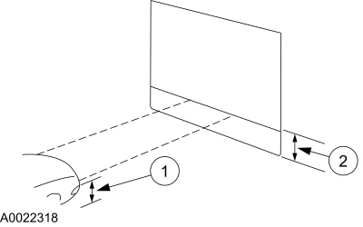
Measure the center of the headlamp height to ground and record the measurement.
 |
-
NOTE: Use a 2.4 m (8 ft) section of masking tape for the horizontal reference line.
-
For vehicles with headlamp bulb center heights
below 95 cm (37.5 inches), place the horizontal reference line equal to
the headlamp bulb center height.
-
For vehicles with headlamp bulb center heights
between 95 cm - 105 cm (37.5 - 41.5 inches), place the horizontal
reference line at the headlamp bulb center height minus 1.3 cm (0.5
inch).
-
For vehicles with headlamp bulb center heights
above 105 cm (41.5 inches), place the horizontal reference line at the
headlamp bulb center height minus 2.5 cm (1.0 inch).
-
For vehicles with headlamp bulb center heights
below 95 cm (37.5 inches), place the horizontal reference line equal to
the headlamp bulb center height.
-
NOTE: Carry out this procedure in a dark environment to effectively see the headlamp beam pattern.
Turn the low beam headlamps on to illuminate the wall or screen and open the hood.
-
NOTE: The cut off of the beam pattern is the horizontal line of the beam pattern where there is MAXIMUM change between light and dark.
On the wall or screen, locate the cut off of the beam pattern.
VOR-type headlamps
NOTE: Procedure applies to both left and right headlamps with VOR molded on lens.
-
NOTE: The appearance of the VOR beam pattern may vary between vehicles.
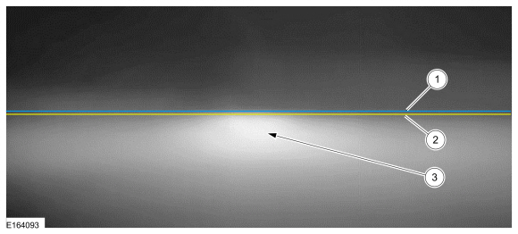
There is a distinct cutoff in the right portion of the beam pattern.
-
-
1 - Horizontal reference line
-
2 - Cut off
-
3 - High intensity zone
-
1 - Horizontal reference line
 |
-
NOTE: Align one headlamp while covering the other headlamp.
Align the headlamps to the horizontal reference line. Adjust the headlamp as necessary using the headlamp adjusting screw.
-
Repeat the previous step for the remaining headlamp.
VOL-type headlamps
NOTE: Procedure applies to both left and right headlamps with VOL molded on lens.
-
NOTE: The appearance of the VOL beam pattern may vary between vehicles.
For VOL-type headlamps, there is a distinct cutoff in the left portion of the beam pattern. The edge of this cutoff should be positioned 5 CM (2 in) below the horizontal reference line.
-
-
1 - Horizontal reference line
-
2 - Cut off
-
3 - High intensity zone
-
1 - Horizontal reference line
 |
-
NOTE: Align one headlamp while covering the other headlamp.
Align the headlamps to the horizontal reference line. Adjust the headlamp as necessary using the headlamp adjusting screw.
-
Repeat the previous step for the remaining headlamp.
 General Procedures - Front Fog Lamp Adjustment
Adjustment
NOTE:
Horizontal aim is not adjustable. Consult your state
vehicle inspection center for recommended tolerance ranges for visual
aiming...
 Removal and Installation - Front Fog Lamp Bulb
Special Tool(s) /
General Equipment
Interior Trim Remover
Removal
NOTE:
LH side shown, RH side similar.
NOTE:
Removal steps in this procedure may contain installation details...
Other information:
Ford Ecosport 2014-2025 Service and Repair Manual: Removal and Installation - Tailgate Latch
Removal NOTE: Removal steps in this procedure may contain installation details. All vehicles Remove the liftgate trim panel. Refer to: Liftgate Trim Panel (501-05 Interior Trim and Ornamentation, Removal and Installation). Vehicles with push button start Disconnect the electrical connectors from the tailgate latch...
Ford Ecosport 2014-2025 Service and Repair Manual: Description and Operation - Pump Assembly
Fluid Pump and Transmission Fluid Filter Components Item Description 1 Torque converter 2 Torque converter housing 3 Transmission fluid filter 4 Pump assembly 5 Pump-to-torque converter housing bolt 6 Tr..
Categories
- Manuals Home
- 2nd Gen Ford Ecosport Service Manual (2014 - 2025)
- Climate Control System - General Information
- Removal and Installation - Front Seat
- Service Information
- Body and Paint
- Automatic Transmission - 6-Speed Automatic Transmission – 6F35
Removal and Installation - Front Stabilizer Bar
Special Tool(s) / General Equipment
Tie Rod End Remover Transmission JackRemoval
NOTICE: Suspension fasteners are critical parts that affect the performance of vital components and systems. Failure of these fasteners may result in major service expense. Use the same or equivalent parts if replacement is necessary. Do not use a replacement part of lesser quality or substitute design. Tighten fasteners as specified.
NOTE: Removal steps in this procedure may contain installation details.
NOTICE: Disconnect the b