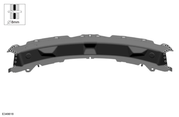
Ford Ecosport: Front End Sheet Metal Repairs / Removal and Installation - Cowl Panel
Special Tool(s) / General Equipment
| Resistance Spotwelding Equipment | |
| 8 mm Drill Bit | |
| MIG/MAG Welding Equipment | |
| Spot Weld Drill Bit | |
| Locking Pliers |
Materials
| Name | Specification |
|---|---|
| Seam Sealer TA-2-B, 3M™ 08308, LORD Fusor® 803DTM |
- |
Removal
NOTE: Factory welds may be substituted with resistance or metal inert gas (MIG) plug welds. Resistance welds may not be placed directly over original location. They must be placed adjacent to original location and match factory welds in quantity. Metal inert gas (MIG) plug welds must equal factory welds in both location and quantity.
NOTE: Adequately protect all adjacent areas against cutting, grinding and welding procedures.
-
Depower the SRS .
Refer to: Supplemental Restraint System (SRS) Depowering (501-20B Supplemental Restraint System, General Procedures).
-
Remove the hood.
Refer to: Hood (501-02 Front End Body Panels, Removal and Installation).
-
Remove the cowl panel grille and cowl panel.
Refer to: Cowl Panel Grille (501-02 Front End Body Panels, Removal and Installation).
Refer to: Cowl Panel (501-02 Front End Body Panels, Removal and Installation).
-
Remove the windshield wiper motor and associated linkage.
Refer to: Windshield Wiper Motor (501-16 Wipers and Washers, Removal and Installation).
Refer to: Wiper Linkage Assembly (501-16 Wipers and Washers, Removal and Installation).
-
Remove the windshield glass.
Refer to: Fixed Glass (501-11 Glass, Frames and Mechanisms, General Procedures).
-
If Required:
Dimensionally restore the vehicle to pre-damage condition.
Refer to: Body and Frame (501-26 Body Repairs - Vehicle Specific Information and Tolerance Checks, Description and Operation).
-
Remove the instrument panel and console.
Refer to: Floor Console (501-12 Instrument Panel and Console, Removal and Installation).
Refer to: Instrument Panel (501-12 Instrument Panel and Console, Removal and Installation).
-
Position the carpet, electrical modules and wiring harnesses away from the working area.
-
NOTE: Pay particular attention to the location of adhesives or sealers to aid in installation.
Remove the welds and the cowl panel.
Use the General Equipment: Spot Weld Drill Bit
 |
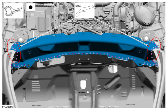
Installation
NOTICE: If refinishing cure temperatures exceed 60° C (140° F), the charge port light ring on plug-in vehicles must be removed.
NOTE: Factory welds may be substituted with resistance or metal inert gas (MIG) plug welds. Resistance welds may not be placed directly over original location. They must be placed adjacent to original location and match factory welds in quantity. Metal inert gas (MIG) plug welds must equal factory welds in both location and quantity.
NOTE: Adequately protect all adjacent areas against cutting, grinding and welding procedures.
-
Drill plug weld holes.
Use the General Equipment: 8 mm Drill Bit
 |
-
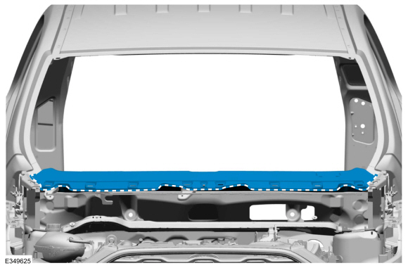
Install, properly position, clamp and weld the replacement cowl panel.
Use the General Equipment: Locking Pliers
Use the General Equipment: Resistance Spotwelding Equipment
Use the General Equipment: MIG/MAG Welding Equipment
 |
-
Dress all welds as required using typical metal finishing techniques and materials.
-
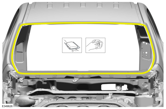
Seam Sealing:
All seams must be sealed to production level.
Material: Seam Sealer / TA-2-B, 3M™ 08308, LORD Fusor® 803DTM
 |
-
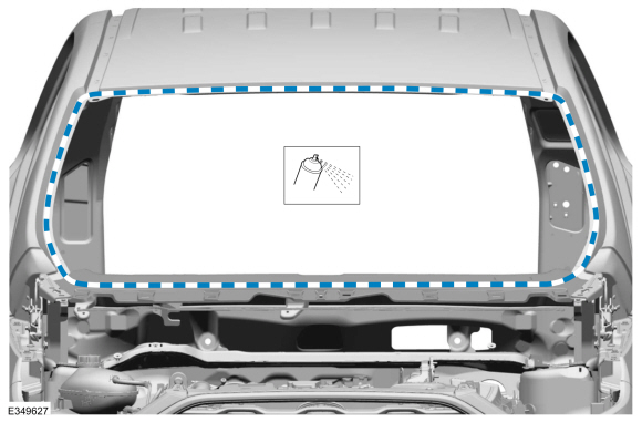
Sand to remove old adhesive, paint, e-coat and clean.
 |
-
Apply a Ford approved epoxy-based primer and allow to dry.
 |
-
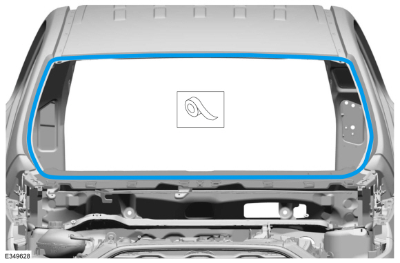
Mask the windshield channel.
 |
-
Refinish the entire repair using a Ford approved paint system.
-
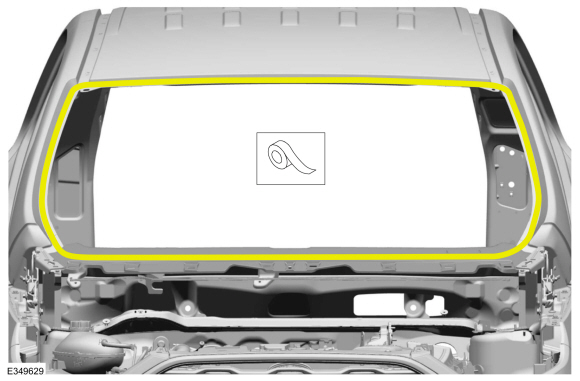
Remove the masking material from the windshield channel.
 |
-
VIN Plate:
Install a new VIN plate.
Refer to: Identification Codes (100-01 Identification Codes, Description and Operation).
-
Install the windshield glass.
Refer to: Fixed Glass (501-11 Glass, Frames and Mechanisms, General Procedures).
-
Restore corrosion protection.
Refer to: Corrosion Prevention (501-25 Body Repairs - General Information, General Procedures).
-
Reposition the wiring harnesses, electrical modules and carpet in original location.
-
Install the instrument panel and console.
Refer to: Instrument Panel (501-12 Instrument Panel and Console, Removal and Installation).
Refer to: Floor Console (501-12 Instrument Panel and Console, Removal and Installation).
-
Install the windshield wiper components.
Refer to: Windshield Wiper Motor (501-16 Wipers and Washers, Removal and Installation).
Refer to: Wiper Linkage Assembly (501-16 Wipers and Washers, Removal and Installation).
-
Install the cowl panel grille and the cowl panel.
Refer to: Cowl Panel Grille (501-02 Front End Body Panels, Removal and Installation).
Refer to: Cowl Panel (501-27 Front End Sheet Metal Repairs, Removal and Installation).
-
Install the hood and align the hood.
Refer to: Hood (501-02 Front End Body Panels, Removal and Installation).
Refer to: Hood Alignment (501-03 Body Closures, General Procedures).
-
Repower the SRS .
Refer to: Supplemental Restraint System (SRS) Repowering (501-20B Supplemental Restraint System, General Procedures).

 Removal and Installation - Dash Panel
Special Tool(s) /
General Equipment
Interior Trim Remover
8 mm Drill Bit
MIG/MAG Welding Equipment
Spot Weld Drill Bit
Locking Pliers
Materials
Name
Specification
Seam SealerTA-2-B, 3M™ 08308, LORD Fusor® 803DTM
-
Removal
NOTE:
Roof removed for clarity...
Other information:
Ford Ecosport 2014-2026 Service and Repair Manual: Diagnosis and Testing - Reversing Lamps
DTC Chart: BCM Diagnostics in this manual assume a certain skill level and knowledge of Ford-specific diagnostic practices. REFER to: Diagnostic Methods (100-00 General Information, Description and Operation). BCM DTC Chart DTC Description Action B1277:11 Reverse Lamp: ..
Ford Ecosport 2014-2026 Service and Repair Manual: Removal and Installation - Wheel Knuckle Bushing
Special Tool(s) / General Equipment Hydraulic Press Removal NOTE: Removal steps in this procedure may contain installation details. Remove the wheel knuckle. Refer to: Wheel Knuckle - Vehicles With: Rear Drum Brakes (204-02B Rear Suspension - AWD, Removal and Installation). Remove the rear toe adjustment retainers and remove the w..
Categories
- Manuals Home
- 2nd Gen Ford Ecosport Service Manual (2014 - 2026)
- Removal and Installation - Evaporative Emission Canister Purge Valve
- Engine
- Removal and Installation - Roof Rail
- Body and Paint
- Service Information
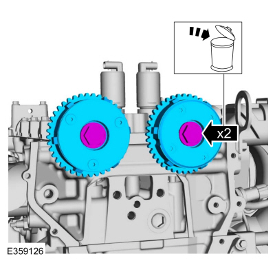
Removal and Installation - Variable Camshaft Timing (VCT) Unit
Removal
NOTICE: During engine repair procedures, cleanliness is extremely important. Any foreign material, including any material created while cleaning gasket surfaces, that enters the oil passages, coolant passages or the oil pan can cause engine failure.
Remove the timing chain.Refer to: Timing Chain (303-01C Engine - 2.0L Duratec-HE (129kW/175PS), Removal and Installation).
Remove the bolts and VCT units.
Discard the bolts.