Ford Ecosport: Engine - 2.0L Duratec-HE (129kW/175PS) / Removal and Installation - Crankshaft Pulley
Special Tool(s) / General Equipment
 |
303-1521 Alignment Tool, Crankshaft Position Sensor TKIT-2010C-FLM |
 |
303-1686 Holding Tool, Camshaft |
 |
303-1689 Holding Tool, Crank Damper |
 |
303-507 Timing Peg, Crankshaft TDC TKIT-2001N-FLM TKIT-2001N-ROW |
| Trolley Jack | |
| Wooden Block | |
Removal
NOTICE: Do not loosen or remove the crankshaft pulley bolt without first installing the special tools as instructed in this procedure. The crankshaft pulley and the crankshaft timing sprocket are not keyed to the crankshaft. The crankshaft, the crankshaft sprocket and the pulley are fitted together by friction. For that reason, the crankshaft sprocket is also unfastened if the pulley bolt is loosened. Before any repair requiring loosening or removal of the crankshaft pulley bolt, the crankshaft and camshafts must be locked in place by the special service tools, otherwise severe engine damage can occur.
NOTICE: During engine repair procedures, cleanliness is extremely important. Any foreign material, including any material created while cleaning gasket surfaces, that enters the oil passages, coolant passages or the oil pan can cause engine failure.
-
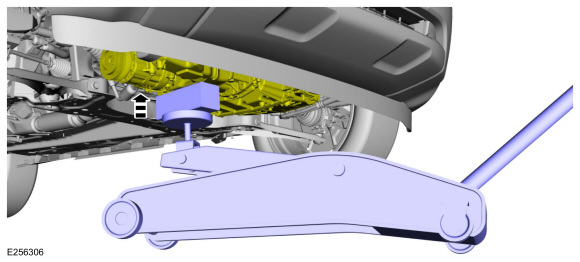
With the vehicle in NEUTRAL, position it on a hoist.
Refer to: Jacking and Lifting - Overview (100-02 Jacking and Lifting, Description and Operation).
-
Remove the following items:
-
Remove the air cleaner outlet pipe.
Refer to: Air Cleaner Outlet Pipe (303-12C Intake Air Distribution and Filtering - 2.0L Duratec-HE (129kW/175PS), Removal and Installation).
-
Remove the RH front fender splash shield.
Refer to: Fender Splash Shield (501-02 Front End Body Panels, Removal and Installation).
-
Remove the accessory drive belt.
Refer to: Accessory Drive Belt (303-05C Accessory Drive - 2.0L Duratec-HE (129kW/175PS), Removal and Installation).
-
Remove the air cleaner outlet pipe.
-
-
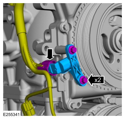
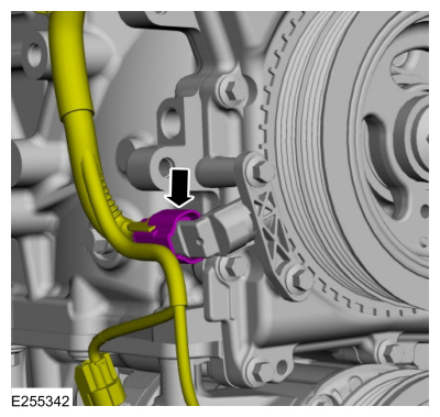
Disconnect the CKP sensor electrical connector.
-
Remove the bolts and the CKP sensor.
-
Disconnect the CKP sensor electrical connector.
 |
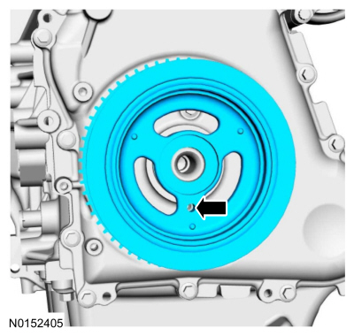
-
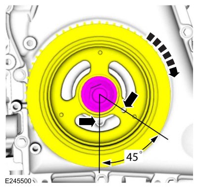
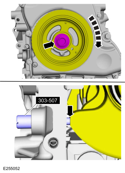
Turn the crankshaft until piston No.1 is 45 degrees before BTDC by
using the guide holes on the engine front cover and the crankshaft
pulley.
 |
-
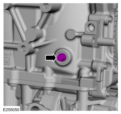
Remove the engine plug bolt.
 |
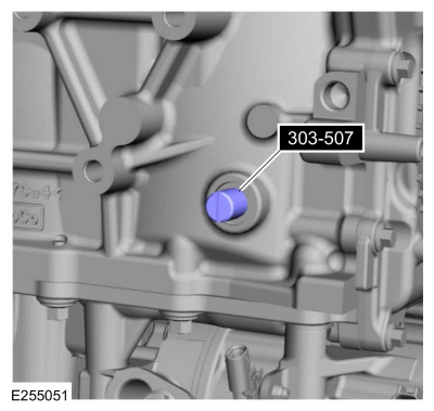
- Install Special Service Tool: 303-507 Timing Peg, Crankshaft TDC.
 |
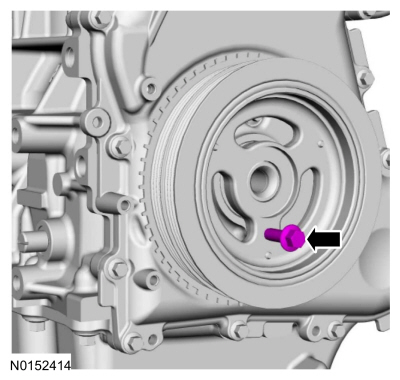
-
NOTE: The special tool will contact the crankshaft and prevent it from turning past TDC . However, the crankshaft can still be rotated in the counterclockwise direction. The crankshaft must remain at the TDC position during the crankshaft pulley removal and installation.
Install the special tool and using the crankshaft pulley bolt, turn the crankshaft clockwise slowly until contact is made with the special tool.
Use Special Service Tool: 303-507 Timing Peg, Crankshaft TDC.
 |
-
Remove the RH and LH CMP sensors.
Refer to: Camshaft Position (CMP) Sensor (303-14C Electronic Engine Controls - 2.0L Duratec-HE (129kW/175PS), Removal and Installation).
-
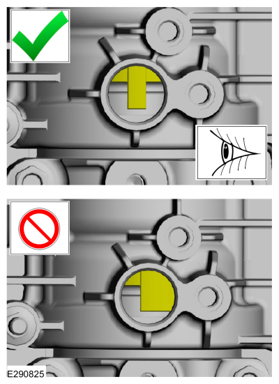
NOTE: Exhaust camshaft shown, intake camshaft similar.
NOTE: The camshaft trigger wheels are offset. If the camshaft trigger wheels are not correctly aligned, the camshaft holding tools will not be able to be installed in the next step.
Make sure the camshaft trigger wheels are correctly aligned as shown. If the trigger wheels are not correctly aligned, remove the TDC Timing Peg and rotate the crankshaft three-fourths of a revolution clockwise and repeat steps 6 and 7 of this removal procedure.
 |
-
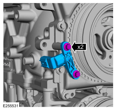
NOTICE: The Camshaft Holding Tool is for camshaft alignment only. Using this tool to prevent engine rotation can result in engine damage.
Install Special Service Tool: 303-1686 Holding Tool, Camshaft.
 |
-
Release the coolant hose retainer, degas bottle tabs and position the degas bottle aside.
 |
-
Detach the A/C line retainer and from the engine mount.
 |
-
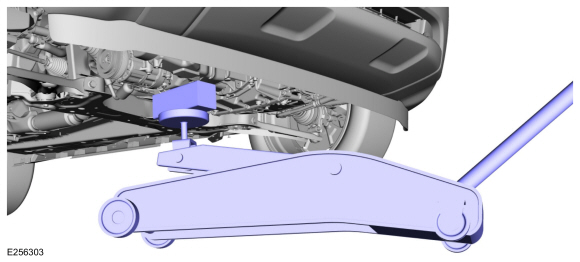
NOTE: Do not support the engine on the Air Conditioning (A/C) compressor.
Using a trolley jack and wooden block, support the engine on the oil pan.
Use the General Equipment: Trolley Jack
Use the General Equipment: Wooden Block
 |
-
-
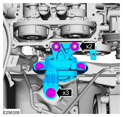
Remove the nuts, bolts and the engine mount.
-
Discard the nuts and bolts.
-
Remove the nuts, bolts and the engine mount.
 |
-
Lower the engine for access to crankshaft pulley.
 |
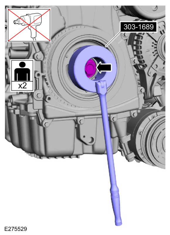
-
NOTICE: The crankshaft must remain in the TDC position during removal of the pulley bolt or damage to the engine can occur. Therefore, the crankshaft pulley must be held in place with the Crank Damper Holding Tool and the bolt should be removed using an air impact wrench (1/2-in drive minimum).
NOTE: If equipped, the crankshaft sprocket diamond washer may come off with the crankshaft pulley.
-
Using the special tool, remove the bolt, washer and the crankshaft pulley.
Use Special Service Tool: 303-1689 Holding Tool, Crank Damper.
-
NOTE: If necessary, retain the original crankshaft pulley bolt to use for the removal of the crankshaft front seal.
Discard the bolt.
-
Using the special tool, remove the bolt, washer and the crankshaft pulley.
 |
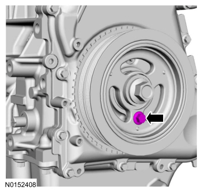
Installation
-
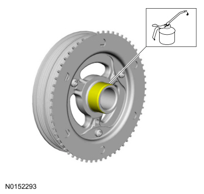
NOTE: Apply clean engine oil on the seal area before installing.
Lubricate the crankshaft pulley with clean engine oil.
 |
-
Position the crankshaft pulley onto the crankshaft with the access hole at the 6 o'clock position.
 |
-
NOTE: This step will correctly align the crankshaft pulley to the crankshaft.
Install an M6 bolt.
 |
-
NOTICE: The crankshaft must remain in the TDC position during installation of the pulley bolt or damage to the engine can occur. Therefore, the crankshaft pulley must be held in place with the Crank Damper Holding Tool and the bolt should be installed using hand tools only.
Using the special tool, install the new crankshaft bolt and washer and tighten.
Use Special Service Tool: 303-1689 Holding Tool, Crank Damper.
Torque:
Stage 1: 74 lb.ft (100 Nm)
Stage 2: 90°
 |
-
Remove the M6 bolt.
 |
-
Raise the engine.
 |
-
-
Install the engine mount and the nuts.
Torque: 59 lb.ft (80 Nm)
-
Install the engine mount bolts.
Torque: 66 lb.ft (90 Nm)
-
Install the engine mount and the nuts.
 |
-
Remove the trolley jack and wooden block.
Use the General Equipment: Trolley Jack
Use the General Equipment: Wooden Block
|
-
Attach the A/C line retainer to the engine mount.
|
-
Position back the degas bottle and connect the tabs and coolant hose retainer.
|
-
Install the CKP sensor and the bolts finger tight.
 |
-
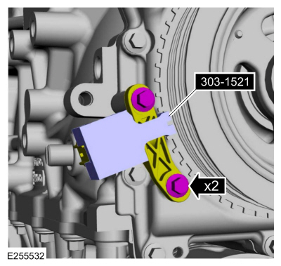
Install the special tool to set the CKP sensor position and tighten the bolts.
Use Special Service Tool: 303-1521 Alignment Tool, Crankshaft Position Sensor.
Torque: 62 lb.in (7 Nm)
 |
- Remove Special Service Tool: 303-1521 Alignment Tool, Crankshaft Position Sensor.
 |
-
Connect the CKP sensor electrical connector.
 |
- Remove Special Service Tool: 303-507 Timing Peg, Crankshaft TDC.
|
-
Install the engine plug bolt.
Torque: 177 lb.in (20 Nm)
|
- Remove Special Service Tool: 303-1686 Holding Tool, Camshaft.
|
-
Install the following items:
-
RH and LH CMP sensors.
Refer to: Camshaft Position (CMP) Sensor (303-14C Electronic Engine Controls - 2.0L Duratec-HE (129kW/175PS), Removal and Installation).
-
Install the accessory drive belt.
Refer to: Accessory Drive Belt (303-05C Accessory Drive - 2.0L Duratec-HE (129kW/175PS), Removal and Installation).
-
Install the RH front fender splash shield.
Refer to: Fender Splash Shield (501-02 Front End Body Panels, Removal and Installation).
-
Install the air cleaner outlet pipe.
Refer to: Air Cleaner Outlet Pipe (303-12C Intake Air Distribution and Filtering - 2.0L Duratec-HE (129kW/175PS), Removal and Installation).
-
RH and LH CMP sensors.
-
Use the Powertrain Control Module (PCM) Misfire Monitor Profile Correction routine in the diagnostic scan tool.
 Removal and Installation - Crankshaft Front Seal
Special Tool(s) /
General Equipment
303-096
(T74P-6150-A)
Installer, Camshaft Front Oil SealTKIT-2009TC-F
303-409
(T92C-6700-CH)
Remover, Crankshaft SealTKIT-1992-FH/FMH/FLMHTKIT-1993-LMH/MH
Removal
NOTICE:
Do not loosen or remove the crankshaft pulley bolt without
first installing the special tools as instructed in this procedure...
 Removal and Installation - Crankshaft Rear Seal
Special Tool(s) /
General Equipment
303-328
(T88P-6701-B1)
Replacer, Rear SealTKIT-1988-FLMTKIT-1988-FTKIT-1988-LM
Oil Drain Equipment
Materials
Name
Specification
Motorcraft® Silicone Gasket and SealantTA-30
WSE-M4G323-A4
Removal
Remove the flexplate...
Other information:
Ford Ecosport 2014-2025 Service and Repair Manual: Removal and Installation - Transfer Case Input Shaft Seal RH
Special Tool(s) / General Equipment 205-153 (T80T-4000-W) Handle 308-875Installer, Inboard Cover SealTKIT-2012A-FLTKIT-2012A-ROW Removal Remove the RH Front halfshaft. Refer to: Front Halfshaft RH - 2...
Ford Ecosport 2014-2025 Service and Repair Manual: Removal and Installation - Steering Column Shrouds
Special Tool(s) / General Equipment Flat-Bladed Screwdriver Interior Trim Remover Removal Lower the steering column adjustment lock. Fully extend and lower the steering column. Release the tabs and disconnect the gap hider from the upper steering column shroud...
Categories
- Manuals Home
- 2nd Gen Ford Ecosport Service Manual (2014 - 2025)
- Removal and Installation - Rear Bumper
- Removal and Installation - Starter Motor
- Body and Paint
- Automatic Transmission - 6-Speed Automatic Transmission – 6F35
- Removal and Installation - Blower Motor
Disassembly - Engine
Special Tool(s) / General Equipment
 205-153
(T80T-4000-W)
205-153
(T80T-4000-W)
Handle
 303-103
(T74P-6375-A)
303-103
(T74P-6375-A)
Holding Tool, Flywheel
T74P-77000-A
TKIT-2009TC-F
 303-1247
VCT Spark Plug Tube Seal Remover and Installer
TKIT-2006UF-FLM
TKIT-2006UF-ROW
 303-15