Ford Ecosport: Supplemental Restraint System / Removal and Installation - Clockspring
Removal
 WARNING:
The following procedure prescribes critical repair steps
required for correct restraint system operation during a crash. Follow
all notes and steps carefully. Failure to follow step instructions may
result in incorrect operation of the restraint system and increases the
risk of serious personal injury or death in a crash.
WARNING:
The following procedure prescribes critical repair steps
required for correct restraint system operation during a crash. Follow
all notes and steps carefully. Failure to follow step instructions may
result in incorrect operation of the restraint system and increases the
risk of serious personal injury or death in a crash.
NOTE: Removal steps in this procedure may contain installation details.
-
Refer to: Pyrotechnic Device Health and Safety Precautions (100-00 General Information, Description and Operation).
WARNING:
Before beginning any service procedure in this
manual, refer to health and safety warnings in section 100-00 General
Information. Failure to follow this instruction may result in serious
personal injury.
-
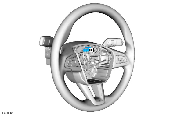
Remove the following items:
-
NOTE: Follow the unique instructions or graphic for this step in installation.
Refer to: Steering Wheel (211-04 Steering Column, Removal and Installation).
-
Refer to: Steering Column Shrouds (501-05 Interior Trim and Ornamentation, Removal and Installation).
-
-
Disconnect the electrical connector.
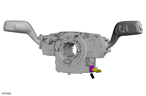 |
-
Remove the screws and the clockspring.
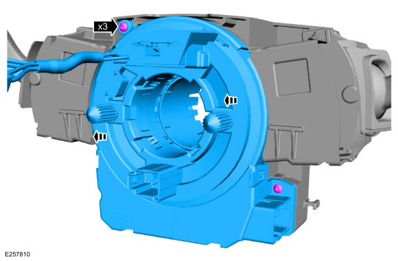 |
Installation
NOTICE: If installing a new clockspring, do not remove the clockspring anti-rotation key until the steering wheel is installed. If the anti-rotation key has been removed before installing the steering wheel, the clockspring must be centered. Failure to follow this instruction may result in component damage and/or system failure.
-
To install, reverse the removal procedure.
-
NOTE: This step is only necessary if adjustment is required.
Adjust the clockspring.
Refer to: Clockspring Adjustment (501-20B Supplemental Restraint System, General Procedures).
-
NOTE: To install, remove the anti-rotation key from a new clockspring after installing the steering wheel.
Install the steering wheel.
Refer to: Steering Wheel (211-04 Steering Column, Removal and Installation).
 |
 Removal and Installation - C-Pillar Side Impact Sensor
Removal
WARNING:
The following procedure prescribes critical repair steps
required for correct restraint system operation during a crash...
 Removal and Installation - Driver Airbag
Special Tool(s) /
General Equipment
Flat-Bladed Screwdriver
Removal
WARNING:
The following procedure prescribes critical repair steps
required for correct restraint system operation during a crash...
Other information:
Ford Ecosport 2014-2026 Service and Repair Manual: Description and Operation - Fuel Tank and Lines - System Operation and Component Description
System Operation Fuel Systems The fuel system supplies the fuel injectors with clean fuel at a controlled pressure. The PCM controls the fuel pump and monitors the fuel pump circuit. The PCM controls the fuel injector ON/OFF cycle duration and determines the correct timing and amount of fuel delivered...
Ford Ecosport 2014-2026 Service and Repair Manual: General Procedures - Exhaust Manifold Cleaning and Inspection
Special Tool(s) / General Equipment Feeler Gauge Cleaning Clean the exhaust manifold using a suitable solvent. Use a plastic scraping tool to clean the gasket sealing surfaces. Inspection NOTE: New exhaust manifold gaskets, studs, nuts and/or bolts must be installed when an exhaust manifold is serviced...
Categories
- Manuals Home
- 2nd Gen Ford Ecosport Service Manual (2014 - 2026)
- Diagnosis and Testing - Evaporative Emissions
- General Procedures - Battery Charging
- Removal and Installation - Blower Motor
- Removal and Installation - Roof Rail
- Removal and Installation - Catalytic Converter
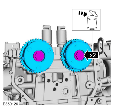
Removal and Installation - Variable Camshaft Timing (VCT) Unit
Removal
NOTICE: During engine repair procedures, cleanliness is extremely important. Any foreign material, including any material created while cleaning gasket surfaces, that enters the oil passages, coolant passages or the oil pan can cause engine failure.
Remove the timing chain.Refer to: Timing Chain (303-01C Engine - 2.0L Duratec-HE (129kW/175PS), Removal and Installation).
Remove the bolts and VCT units.
Discard the bolts.