Ford Ecosport: Information and Entertainment System - General Information / Removal and Installation - Audio Unit Antenna Cable
Removal
NOTE:
Removal steps in this procedure may contain installation details.
NOTE:
The original equipment audio unit antenna cable is part of
the wiring harness and cannot be removed. This procedure refers to
replacement of the cable only by overlaying the cable.
Instrument panel audio unit antenna cable
-
Remove components for access to the instrument panel wiring harness.
-
Remove the FDIM .
Refer to: Front Display Interface Module (FDIM)
(415-00 Information and Entertainment System - General Information)
.
-
Remove the IPC .
Refer to: Instrument Panel Cluster (IPC) (413-01 Instrumentation, Message Center and Warning Chimes, Removal and Installation).
-
Remove the HVAC control module.
Refer to: Heating, Ventilation and Air Conditioning (HVAC) Control
Module (412-00 Climate Control System - General Information, Removal and
Installation).
-
Remove the center air register.
Refer to: Center Registers (412-00 Climate Control System - General Information, Removal and Installation).
-
Remove the glove compartment.
Refer to: Glove Compartment - Remove for Access (501-12 Instrument Panel and Console)
.
-
Position aside the RH front door weatherstrip.
-
Release the clips and remove the front door scuff plate trim panel.
-
Remove the RH lower A-pillar trim panel.
-
Position the RH front door weatherstrip aside.
-
Remove the upper screw.
-
Separate the retainers.
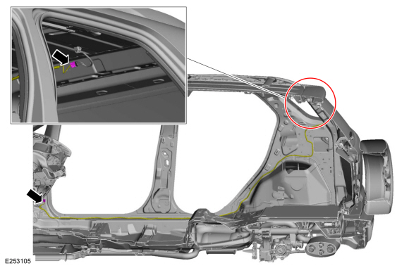
Main body harness audio unit antenna cable
-
Position aside the RH front door weatherstrip.
-
Release the clips and remove the front door scuff plate trim panel.
-
Remove the RH lower A-pillar trim panel.
-
Position the RH front door weatherstrip aside.
-
Remove the upper screw.
-
Separate the retainers.
-
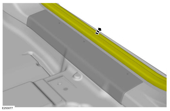
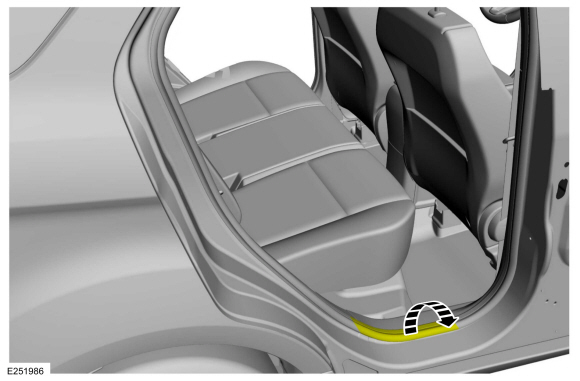
Position the rear door weatherstrip aside.
-
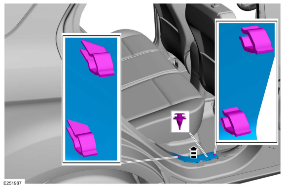
Release the clips and remove the rear door scuff plate trim panel.
-
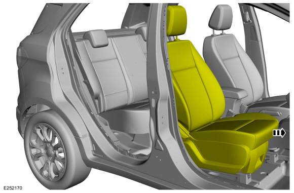
NOTE:
Front seat removed for clarity.
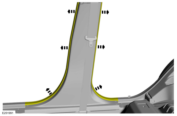
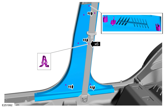
Position the front and rear door weatherstrip aside.
-
Release the clips and locator pin and remove the lower B-pillar trim panel.
-
Position the front seat in the full forward position.
-
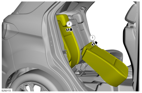
Position the rear seat in the full fold flat position.
-
Position the rear seat cushion in the full forward position.
-
Position the rear seat backrest in the full flat position.
-
Position the rear door weatherstrip aside.
-
Release the clips and the locator pins and remove the C-pillar lower trim panel.
-
Remove the C-pillar lower trim panel.
Refer to: C-Pillar Lower Trim Panel (501-05 Interior Trim and Ornamentation, Removal and Installation).
-
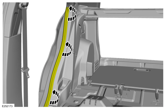
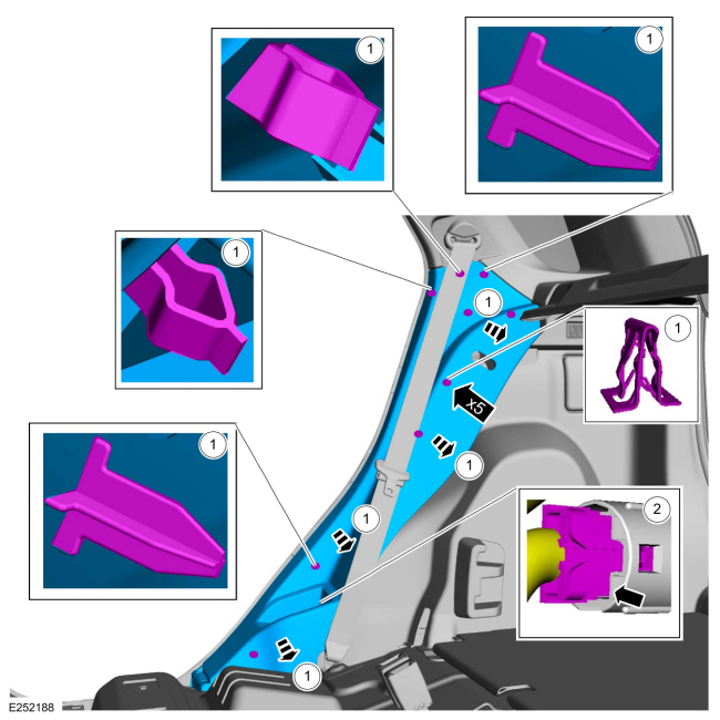
Remove the RH loadspace trim panel.
Refer to: Loadspace Trim Panel (501-05 Interior Trim and Ornamentation, Removal and Installation).
Installation
Instrument panel audio unit antenna cable
-
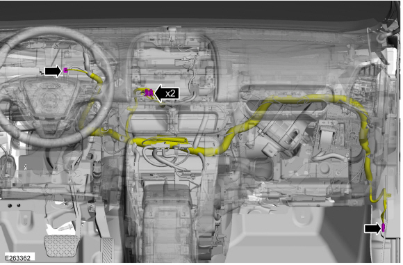
Disconnect the audio unit antenna cable connectors and cut connectors the off the cable.
-
Overlay the audio unit antenna cable and connect the connectors.
Main body harness audio unit antenna cable
-
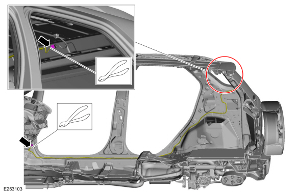
Disconnect the audio unit antenna cable connectors and cut connectors the off the cable.
-
Overlay the audio unit antenna cable and connect the connectors.
All cables
-
Overlay and secure the replacement antenna cable to the wiring harness.
-
To install, reverse the removal procedure.
Removal
Lower the headliner.
Refer to: Headliner - Lowering (501-05 Interior Trim and Ornamentation, Removal and Installation).
Remove the audio unit antenna...
Removal
NOTE:
Removal steps in this procedure may contain installation details.
NOTE:
The original equipment cellular phone antenna cable is part
of the wiring harness and cannot be removed...
Other information:
WARNING:
Batteries contain sulphuric acid, avoid contact with skin, eyes
or clothing. Wear safety goggles when working near the battery to
protect against possible splashing of the acid solution.
WARNING:
EYE CONTACT: If acid comes into contact with the eyes, flush
immediately with plenty of running water for a minimum of 15 minutes...
Removal
NOTE:
Removal steps in this procedure may contain installation details.
Remove the engine appearance cover.
WARNING:
The tensioner is under spring tension. Be careful
when handling the tensioner...



 Removal and Installation - Audio Unit Antenna
 Removal and Installation - Cellular Phone Antenna Cable
