Ford Ecosport: Climate Control System - General Information / General Procedures - Refrigerant System Tests - 2.0L Duratec-HE (129kW/175PS)
Inspection
NOTE: Procedure 1 — Ambient Temperature between 21°C (70°F) and 38°C (100°F)
NOTE: Variable compressors may not stroke up unless the ambient temperatures are above 21°C (70°F) when conducting the pressure mapping procedure. Variable compressor need to see a thermal load on the system in order to create normal operating pressures.
-
Run the engine until it reaches normal operating temperature.
-
Connect the air conditioning service unit to the refrigerant system.
-
Set temperature to the lowest possible temperature
setting with the dual function disabled (if equipped). Manually set
blower on HI. If the vehicle has a fresh air/recirc button, set it to
FRESH. If the vehicle has an A/C switch or compressor on switch, set it to A/C ON.
-
Open all vehicle windows and leave the hood open for the test. Open the rear doors.
-
Confirm the compressor is operating and the engine
cooling fan(s) are operating or engaged. Allow the vehicle to idle until
the suction (low-side) and discharge (high-side) pressures are stable
or fluctuate in a range that repeats.
-
Record the ambient (shop) temperature.
-
Record the discharge pressure. If the pressure is fluctuating, record the average value.
-
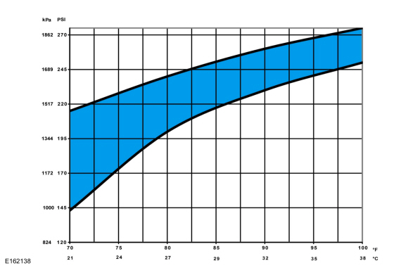
Determine if the discharge pressure falls within the normal operating limits using the Normal Refrigerant Discharge Pressures 21 - 38° C (70 - 100° F) Ambient (30 - 60% Relative Humidity) chart below.
 |
-
Record the suction pressure. If the pressure is fluctuating, record the average value.
-
Determine if the suction pressure falls within the normal operating limits using the Normal Refrigerant Suction Pressures 21 - 38° C (70 - 100° F) Ambient (30 - 60% Relative Humidity) chart below.
 |
-
NOTE: Use the following table to guide diagnosis of the refrigerant system if operating pressures are outside normal limits.
Refer to the chart below.High (Discharge) Pressure Low (Suction) Pressure Component — Causes High Normal to High - Condenser — inadequate airflow.
- Engine — overheating.
Normal to High Normal - Refrigerant overcharge — air in refrigerant.
Normal to Low High - A/C Compressor — low performance.
Normal to Low Normal to High - A/C suction line — partially restricted or plugged. a
Normal to Low Low - Low refrigerant charge — leak in system.
- A/C suction line — partially restricted or plugged. b
Erratic Operation or Compressor Not Running - Ambient Air Temperature (AAT) sensor — poor connection.
- A/C pressure transducer — poor connection.
- Evaporator temperature sensor — poor connection.
- Low refrigerant charge — leak in system.
Additional Possible Components or Causes Associated With Inadequate Compressor Operation - Compressor drive belt — loose
- Compressor clutch — slipping
- Clutch coil open — shorted, or loose mounting
- Control assembly switch — dirty contacts or sticking open
- Clutch wiring circuit — high resistance, open or blown fuse
- Compressor operation interrupted by engine computer
Additional Possible Components or Causes Associated With a Damaged Compressor - Incorrect clutch air-gap
- Suction accumulator — refrigerant oil bleed hose plugged
- Refrigerant leaks
a Low pressure reading will be normal to high if restriction is downstream of service access valve.
b Low pressure reading will be low if restriction is upstream of service access valve.
Inspection
NOTE: Procedure 2 — Ambient Temperature Above 38°C (100°F)
-
Run the engine until it reaches normal operating temperature.
-
Connect the air conditioning service unit to the refrigerant system.
-
Set temperature to the lowest possible temperature
setting with the dual function disabled (if equipped). Manually set
blower on HI. If the vehicle has a fresh air/recirc button, set it to
FRESH. If the vehicle has an A/C switch or compressor on switch, set it to A/C ON.
-
Open all vehicle windows and leave the hood open for the
test. Open the rear hatch and/or rear doors (if equipped).
-
Confirm the compressor is operating and the engine
cooling fan(s) are operating or engaged. Allow the vehicle to idle until
the suction (low-side) and discharge (high-side) pressures are stable
or fluctuate in a range that repeats.
-
Record the ambient (shop) temperature.
-
Record the discharge pressure. If the pressure is fluctuating, record the average value.
-
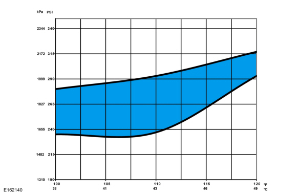
Determine if the discharge pressure falls within the normal operating limits using the Normal Refrigerant Discharge Pressures 38 - 49° C (100 - 120° F) Ambient (15 - 40% Relative Humidity) chart below.
 |
-
Record the suction pressure. If the pressure is fluctuating, record the average value.
-
Determine if the suction pressure falls within the normal operating limits using the Normal Refrigerant Suction Pressures 38 - 49° C (100 - 120° F) Ambient (15 - 40% Relative Humidity) chart below.
 |
-
NOTE: Use the following table to guide diagnosis of the refrigerant system if operating pressures are outside normal limits.
Refer to the chart below.High (Discharge) Pressure Low (Suction) Pressure Component — Causes High Normal to High - Condenser — inadequate airflow.
- Engine — overheating.
Normal to High Normal - Refrigerant overcharge — air in refrigerant.
Normal to Low High - A/C Compressor — low performance.
Normal to Low Normal to High - A/C suction line — partially restricted or plugged. a
Normal to Low Low - Low refrigerant charge — leak in system.
- A/C suction line — partially restricted or plugged. b
Erratic Operation or Compressor Not Running - Ambient Air Temperature (AAT) sensor — poor connection.
- A/C pressure transducer — poor connection.
- Evaporator temperature sensor — poor connection.
- Low refrigerant charge — leak in system.
Additional Possible Components or Causes Associated With Inadequate Compressor Operation - Compressor drive belt — loose
- Compressor clutch — slipping
- Clutch coil open — shorted, or loose mounting
- Control assembly switch — dirty contacts or sticking open
- Clutch wiring circuit — high resistance, open or blown fuse
- Compressor operation interrupted by engine computer
Additional Possible Components or Causes Associated With a Damaged Compressor - Incorrect clutch air-gap
- Suction accumulator — refrigerant oil bleed hose plugged
- Refrigerant leaks
a Low pressure reading will be normal to high if restriction is downstream of service access valve.
b Low pressure reading will be low if restriction is upstream of service access valve.
 General Procedures - Refrigerant Oil Adding - Vehicles With: R1234YF Refrigerant
Special Tool(s) /
General Equipment
Air Conditioning Service Unit
Refrigerant Oil Injector Set
Filling
Refer to the Refrigerant Oil Adding (when new components
are installed) chart below for refrigerant oil adding amounts and
methods of installation...
 General Procedures - Reset the Outside Air Temperature Sensor Learned Values
Configuration
NOTE:
The ambient air temperature sensor is a critical
component for correct Air Conditioning (A/C) and Heating, Ventilation,
and Air Conditioning (HVAC) system operation...
Other information:
Ford Ecosport 2014-2024 Service and Repair Manual: Description and Operation - Rear View Mirrors - System Operation and Component Description
System Operation System Diagram - Exterior, Power Item Description 1 LH exterior mirror 2 Exterior mirror control switch 3 RH exterior mirror System Operation - Exterior, Power All functions of the power mirror feature are integrated into one switch module...
Ford Ecosport 2014-2024 Service and Repair Manual: Removal and Installation - Hood Latch
Removal NOTE: Removal steps in this procedure may contain installation details. If equipped. Disconnect the hood ajar switch electrical connector. Remove the hood latch assembly...
Categories
- Manuals Home
- 2nd Gen Ford Ecosport Service Manual (2014 - 2024)
- Body and Paint
- Automatic Transmission - 6-Speed Automatic Transmission – 6F35
- Removal and Installation - Block Heater
- Removal and Installation - Evaporative Emission Canister Purge Valve
- Removal and Installation - Starter Motor
Removal and Installation - Front Stabilizer Bar
Special Tool(s) / General Equipment
Tie Rod End Remover Transmission JackRemoval
NOTICE: Suspension fasteners are critical parts that affect the performance of vital components and systems. Failure of these fasteners may result in major service expense. Use the same or equivalent parts if replacement is necessary. Do not use a replacement part of lesser quality or substitute design. Tighten fasteners as specified.
NOTE: Removal steps in this procedure may contain installation details.
NOTICE: Disconnect the b