Ford Ecosport: Climate Control System - General Information / General Procedures - Refrigerant Oil Adding - Vehicles With: R1234YF Refrigerant
Special Tool(s) / General Equipment
| Air Conditioning Service Unit | |
| Refrigerant Oil Injector Set |
Filling
-
Refer to the Refrigerant Oil Adding (when new components
are installed) chart below for refrigerant oil adding amounts and
methods of installation.
-
199-FFX1234 Flo Dynamics R1234yf A/C Refrigerant Management Center
Refrigerant Oil Adding (when new components are installed)
Use the General Equipment: Air Conditioning Service UnitComponent Motorcraft® R-1234yf Refrigerant PAG Oil (YN-35) Amount, fl oz ( ml) Method of Adding After installing the A/C Compressor. Service compressor contains full system charge of oil. Oil matching required plus amount collected during recovery. Refer to oil adding steps above. After installing the receiver drier. 2 fl oz (60 ml) plus the amount collected during refrigerant recovery. Inject to low-side service port during system charging. After installing the receiver drier element. 1 fl oz (30 ml) plus the amount collected during refrigerant recovery. Inject to low-side service port during system charging. After installing the condenser core. 1.5 fl oz (45 ml) plus the amount collected during refrigerant recovery. Add directly to inlet port or inject to low-side service port during system charging. After installing the condenser core, and the receiver drier element. 2 fl oz (60 ml) plus the amount collected during refrigerant recovery. Add directly to inlet port or inject to low-side service port during system charging. After installing the evaporator core. 1.5 fl oz (45 ml) plus the amount collected during refrigerant recovery. Add directly to inlet port or inject to low-side service port during system charging. After installing/reassembling the thermostatic expansion valve. Amount collected during refrigerant recovery. Inject to low-side service port during system charging. After installing a refrigerant Hose/Line. 2 fl oz (60 ml) plus the amount collected during refrigerant recovery a. Inject to low-side service port during system charging. After an O-ring Leak Repair. 1 fl oz (30 ml) plus the amount collected during refrigerant recovery b. Inject to low-side service port during system charging. After a service port leak repair. Amount collected during refrigerant recovery. Inject to low-side service port during system charging. a If an excessive amount of Motorcraft® R-1234yf Refrigerant PAG Oil (YN-35) is lost due to a hose rupture/separation or other damage, the total system Motorcraft® R-1234yf Refrigerant PAG Oil (YN-35) capacity must be added. Also, it is necessary to replace the receiver drier. b The amount specified may be used for one or multiple O-ring leak repairs. Do not multiply the Motorcraft® R-1234yf Refrigerant PAG Oil (YN-35) amount by the number of O-ring leaks being repaired.
-
199-FFX1234 Flo Dynamics R1234yf A/C Refrigerant Management Center
Oil Injection Using a Refrigerant Oil Injector Set
-
NOTE: Fluorescent refrigerant system dye is added to the refrigerant system at the factory to assist in refrigerant system leak diagnosis using a Rotunda-approved UV black light. It is not necessary to add additional dye to the refrigerant system before diagnosing leaks, even if a significant amount of refrigerant has been removed from the system. Replacement suction accumulators, receiver driers and receiver drier elements are shipped with a fluorescent dye wafer included in the desiccant bag which dissolves after approximately 30 minutes of continuous A/C operation. It is not necessary to add dye after flushing the refrigerant system because a new suction accumulator, receiver drier or receiver drier element is installed as part of the flushing procedure.
NOTE: Before using the R-1234yf Fluorescent Dye Injector/Refrigerant Oil Injector Set for the first time, refer to the equipment manufacturer's instructions.
NOTE: Refrigerant system pressure should be between 413-551 kPa (60-80 psi) at 24° C (75° F) with the engine off and cool.
Adjust the oil injector piston and fill the oil injector with the correct amount of clean, new Motorcraft® R-1234yf Refrigerant PAG Oil (YN-35).
-
258-90027 Airsept 134a and 1234yf A/C Refrigerant Large Oil Injector
Use the General Equipment: Refrigerant Oil Injector Set
-
258-90027 Airsept 134a and 1234yf A/C Refrigerant Large Oil Injector
-
Install the oil injector to the low-side service port valve.
-
NOTE: Make sure all tools and hoses are clear of the engine cooling fan and drive belt before starting the engine. Failure to keep tools and hoses clear from the engine cooling fan and drive belt results in damage to the tools and/or vehicle.
Start the engine and using the HVAC controls press the A/C system on button. Turn the oil injector piston clockwise and inject the refrigerant oil.
Inspection
Compressor Type
-
NOTICE: An A/C refrigerant analyzer must be used before the recovery of any vehicle's A/C refrigerant. Failure to do so puts the shop's bulk refrigerant at risk of contamination. If the vehicle's A/C refrigerant is contaminated, refer the customer to the service facility that carried out the last A/C service. If the customer wishes to pay the additional cost, use the A/C recovery equipment that is designated for recovering contaminated A/C refrigerant. Dispose of all contaminated A/C refrigerant as hazardous waste. For all equipment, follow the manufacturer's instructions.
NOTICE: Motorcraft® R-1234yf Refrigerant PAG Oil (YN-35) only must be used as a refrigerant system lubricant. Addition of any oil other than Motorcraft® R-1234yf Refrigerant PAG Oil (YN-35) to the refrigerant system will damage the A/C compressor and contaminate the refrigerant system.
NOTICE: During normal A/C operation, oil is circulated through the system with the refrigerant, and a small amount is retained in each component. If certain components of the system are removed, some of the refrigerant oil will go with the component. To maintain the original total oil charge, it is necessary to compensate for the oil lost by adding oil to the system with the new part.
NOTICE: Perform an oil balance when replacing a compressor where system flush will not be performed.
NOTE: The purpose of oil balance is to make sure the amount of oil in the system is not increased or decreased as a result of the replacement component(s).
NOTE: New compressors come fully charged with Motorcraft® R-1234yf Refrigerant PAG Oil (YN-35). The old compressor is only partially charged because some of the oil is elsewhere in the A/C system.
Verify the location of the drain plug by compressor type. Once the compressor type has been identified, proceed to appropriate compressor type below for compressor oil matching steps.
-
NOTE: Type 1: (IVDC) Internal Variable Displacement Air Conditioning (A/C) Compressor
 |
-
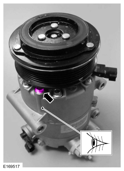
NOTE: Type 2: (EVDC) External Variable Displacement Air Conditioning (A/C) Compressor
 |
-
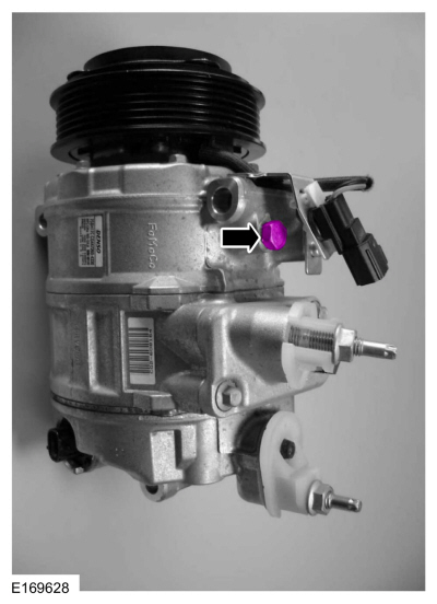
NOTE: Type 3: (EVDC) External Variable Displacement Air Conditioning (A/C) Compressor
 |
-
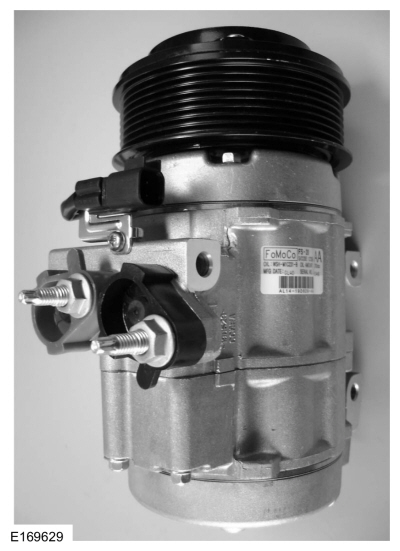
NOTE: Type 4: Fixed Air Conditioning (A/C) Compressor
 |
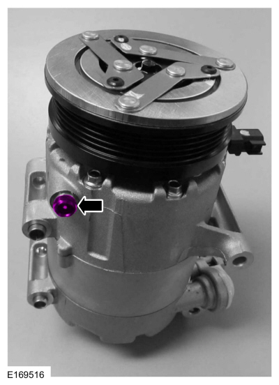
Type 1
-
NOTICE: Make sure the old A/C compressor shaft is rotating and not just the A/C pulley.
Remove the oil drain bolt and rotate the old A/C compressor clutch 6 to 8 revolutions while collecting oil in a clean measuring device.
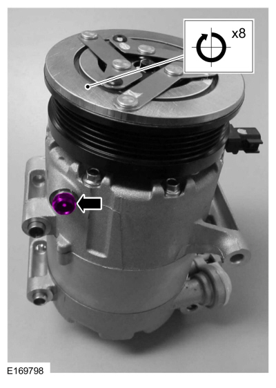 |
-
Install the oil drain bolt in the old A/C compressor.
|
-
Remove the suction and discharge port seal cap from the new A/C compressor.
-
NOTICE: Make sure the new A/C compressor shaft is rotating and not just the A/C pulley.
Remove the drain bolt and rotate the new A/C compressor clutch 6 to 8 revolutions while collecting oil in a clean measuring device.
|
-
Measure the amount of oil drained from the old A/C compressor and add the same amount of new oil to the new A/C compressor.
-
Install the oil drain bolt in the new A/C compressor.
Torque: 177 lb.in (20 Nm)
|
-
Install the suction and discharge port seal cap on the new A/C compressor.
Type 2
-
Remove the A/C clutch and A/C clutch field coil from the old A/C
compressor. Refer to Air Conditioning (A/C) Clutch and Air Conditioning
(A/C) Clutch Field Coil procedure in Group 412.
-
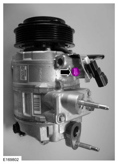
Remove the oil drain bolt from the old A/C compressor.
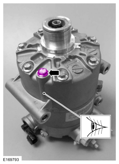 |
-
Press the suction damper to allow proper ventilation while draining the oil from the old A/C compressor.
 |
-
Drain the oil from the old A/C compressor, collecting oil in a clean measuring device.
-
Install the oil drain bolt in the old A/C compressor.
|
-
Remove the A/C clutch and A/C clutch field coil from the new A/C
compressor. Refer to Air Conditioning (A/C) Clutch and Air Conditioning
(A/C) Clutch Field Coil procedure in Group 412.
-
Remove the oil drain bolt from the new A/C compressor.
|
-
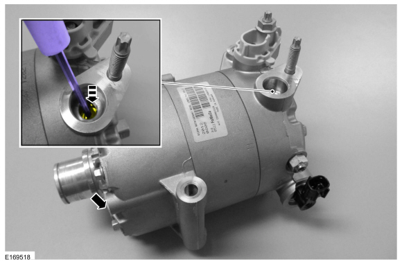
Remove the suction port seal cap.
-
Press the suction damper to allow proper ventilation while draining the oil from the new A/C compressor.
|
-
Drain the oil from the new A/C compressor, collecting oil in a clean measuring device.
-
Measure the amount of oil drained for the old A/C compressor and add the same amount of new oil to the new A/C compressor.
-
Install the oil drain bolt in the new A/C compressor.
Torque: 80 lb.in (9 Nm)
|
-
Install the suction port seal cap.
-
Install the A/C clutch and A/C clutch field coil on the new A/C
compressor. Refer to Air Conditioning (A/C) Clutch and Air Conditioning
(A/C) Clutch Field Coil procedure in Group 412.
Type 3
-
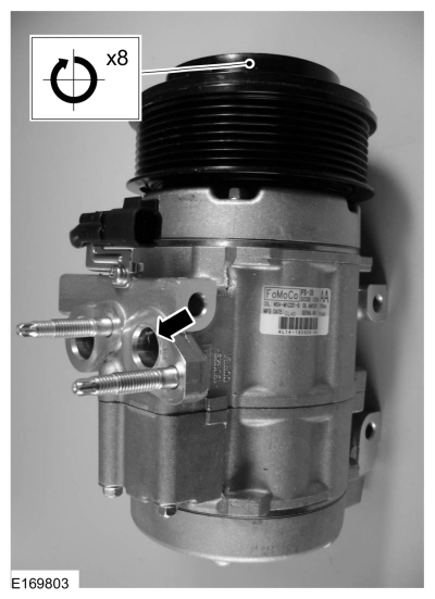
NOTICE: Make sure the old A/C compressor shaft is rotating and not just the A/C pulley.
Remove the oil drain bolt and rotate the old A/C compressor clutch 6 to 8 revolutions while collecting oil in a clean measuring device.
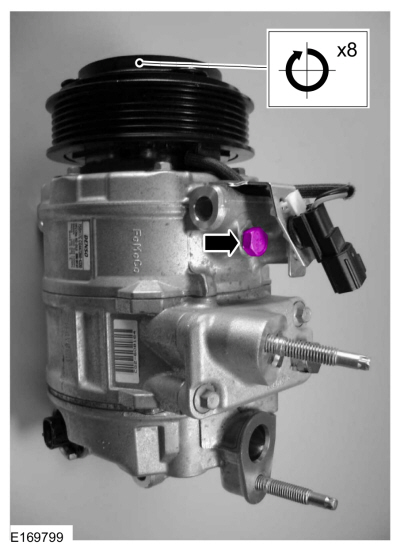 |
-
Install the oil drain bolt in the old A/C compressor.
 |
-
Remove the suction and discharge port seal cap from the new A/C compressor.
-
NOTICE: Make sure the new A/C compressor shaft is rotating and not just the A/C pulley.
Remove the drain bolt and rotate the new A/C compressor clutch 6 to 8 revolutions while collecting oil in a clean measuring device.
|
-
Measure the amount of oil drained for the old A/C compressor and add the same amount of new oil to the new A/C compressor.
-
Install the oil drain bolt in the newA/C compressor.
Torque: 22 lb.ft (30 Nm)
|
-
Install the suction and discharge port seal cap on the new A/C compressor.
Type 4
-
NOTICE: Make sure the old A/C compressor shaft is rotating and not just the A/C pulley.
Rotate the old A/C compressor clutch 6 to 8 revolutions while collecting oil in a clean measuring device from the A/C compressor discharge port.
 |
-
Remove the suction and discharge port seal cap from the new A/C compressor.
-
NOTICE: Make sure the new A/C compressor shaft is rotating and not just the A/C pulley.
Tilt the new A/C compressor on an angle and rotate the new A/C compressor clutch 6 to 8 revolutions while collecting oil in a clean measuring device from the A/C compressor discharge port.
|
-
Measure the amount of oil drained from the old A/C compressor and add the same amount of new oil to the new A/C compressor.
-
Install the suction and discharge port seal cap on the new A/C compressor.
Filling
-
NOTICE: An A/C refrigerant analyzer must be used before the recovery of any vehicle's A/C refrigerant. Failure to do so puts the shop's bulk refrigerant at risk of contamination. If the vehicle's A/C refrigerant is contaminated, refer the customer to the service facility that carried out the last A/C service. If the customer wishes to pay the additional cost, use the A/C recovery equipment that is designated for recovering contaminated A/C refrigerant. Dispose of all contaminated A/C refrigerant as hazardous waste. For all equipment, follow the manufacturer's instructions.
NOTICE: Motorcraft® R-1234yf Refrigerant PAG Oil (YN-35) only must be used as a refrigerant system lubricant. Addition of any oil other than Motorcraft® R-1234yf Refrigerant PAG Oil (YN-35) to the refrigerant system will damage the A/C compressor and contaminate the refrigerant system.
NOTICE: During normal A/C operation, oil is circulated through the system with the refrigerant, and a small amount is retained in each component. If certain components of the system are removed, some of the refrigerant oil will go with the component. To maintain the original total oil charge, it is necessary to compensate for the oil lost by adding oil to the system with the new part.
NOTICE: Make sure the equipment is clean and free of foreign material.
REFER to the chart above for refrigerant oil adding amounts and methods of installation.
 General Procedures - Refrigerant Identification Testing - Vehicles With: R1234YF Refrigerant
Special Tool(s) /
General Equipment
Refrigerant Identification Equipment
Activation
NOTE:
Use Refrigerant Identification Equipment to identify
gas samples taken directly from the refrigeration system or storage
containers prior to recovering or charging the refrigerant system...
 General Procedures - Refrigerant System Tests - 2.0L Duratec-HE (129kW/175PS)
Inspection
NOTE:
Procedure 1 — Ambient Temperature between 21°C (70°F) and 38°C (100°F)
NOTE:
Variable compressors may not stroke up unless the ambient
temperatures are above 21°C (70°F) when conducting the pressure mapping
procedure...
Other information:
Ford Ecosport 2014-2025 Service and Repair Manual: Removal and Installation - Active Grille Shutter Actuator
Removal NOTE: Removal steps in this procedure may contain installation details. Remove the active grill shutter. Refer to: Active Grille Shutter - 2.0L Duratec-HE (125kW/170PS) – MI4 (501-02 Front End Body Panels, Removal and Installation)...
Ford Ecosport 2014-2025 Service and Repair Manual: Removal and Installation - Main Control Valve Body
Removal Remove the main control cover. Refer to: Main Control Cover (307-01B Automatic Transmission - 6-Speed Automatic Transmission – 6F35, Removal and Installation). Disconnect the TR sensor electrical connector...
Categories
- Manuals Home
- 2nd Gen Ford Ecosport Service Manual (2014 - 2025)
- Diagnosis and Testing - Body Control Module (BCM)
- Removal and Installation - Front Seat
- Removal and Installation - Fuel Pump and Sender Unit
- Diagnosis and Testing - Evaporative Emissions
- Engine
Removal and Installation - Oil Pressure Switch
Materials
Name Specification Motorcraft® Thread Sealant with PTFETA-24-B WSK-M2G350-A2
Removal
NOTE: Removal steps in this procedure may contain installation details.
With the vehicle in NEUTRAL, position it on a hoist.Refer to: Jacking and Lifting - Overview (100-02 Jacking and Lifting, Description and Operation).
If equipped, remove the bolts and the underbody shield.