Ford Ecosport: Suspension System - General Information / General Procedures - Rear Toe Adjustment - AWD
Special Tool(s) / General Equipment
| Wheel Alignment System |
Adjustment
NOTICE: Do not use any tools or equipment to move the wheel and tire assembly or suspension components while checking for relative movement. Suspension damage may occur. The use of tools or equipment will also create relative movement that may not exist when using hand force. Relative movement must be measured using hand force only.
NOTE: Make sure that the vehicle is standing on a level surface.
-
Check the toe setting.
Refer to: Specifications (204-00 Suspension System - General Information, Specifications).
-
Using alignment equipment and the manufacturer's instructions, check the rear toe setting on both sides.
Use the General Equipment: Wheel Alignment System
-
NOTICE: The cam nut and cam bolt area must be free of foreign material to make sure of correct clamping.
NOTE: Clean the general area of the joint to prevent foreign material from entering the joint. Clean the area using only mild liquids.
On both sides.
Loosen the toe link bolt counterclockwise (CCW) through 2 complete turns.
 |
-
Bounce the vehicle to make sure that the suspension is in its normal, at-rest position.
-
NOTE: Groove assembled inboard on bushing and outboard of the vehicle.
On both sides.
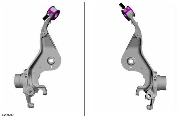
Confirm the rubber stopper must be assemled with tab orientation as shown in image.
 |
-
NOTE: Make sure that the rubber stopper correctly located.
On both sides.
Rubber stopper must be fitted in inner ring bush groove.
 |
-
On both sides. Adjust the toe setting.
Rotate the toe link nut to achieve the specified toe setting.
 |
-
NOTE: Only tighten the nut and bolt finger tight at this stage.
On both sides.
Make sure that nut and inner tube guide on same orientation
 |
-
Recheck the toe settings and adjust as necessary.
-
NOTICE: Tighten the suspension bushing fasteners with the suspension loaded or with the weight of the vehicle resting on the wheels and tires, otherwise incorrect clamp load and bushing damage may occur.
NOTE: Make sure that the mating faces are clean and free of foreign material.
On both sides.
Tighten the toe link nut and bolt.
Torque:
Stage 1: 177 lb.in (20 Nm)
Stage 2: 92 lb.ft (125 Nm)
 |
 General Procedures - Front Toe Adjustment
Special Tool(s) /
General Equipment
Wheel Alignment System
Adjustment
NOTE:
Make sure that the vehicle is standing on a level surface...
 General Procedures - Ride Height Measurement
Special Tool(s) /
General Equipment
Surface Gauge
Check
Ride Height Measurement - Front
NOTE:
Make sure that the vehicle is positioned on a flat,
level surface and the tires are inflated to the correct pressure...
Other information:
Ford Ecosport 2014-2026 Service and Repair Manual: Removal and Installation - Front Halfshaft RH - 2.0L Duratec-HE (125kW/170PS) – MI4, AWD
Special Tool(s) / General Equipment 204-161 (T97P-1175-A) Installer, HalfshaftTKIT-1997-LM2TKIT-1997-F/FM2TKIT-1997-FLM2 205-D070 (D93P-1175-B) Remover, Front Wheel Hub 211-001 (TOOL-3290-D) Remover, Tie-Rod End Removal NOTE: Removal steps in this procedure may contain installation details...
Ford Ecosport 2014-2026 Service and Repair Manual: Removal and Installation - Upper Arm
Special Tool(s) / General Equipment Vehicle/Axle Stands Removal NOTICE: Suspension fasteners are critical parts that affect the performance of vital components and systems. Failure of these fasteners may result in major service expense...

 WARNING:
Wear eye and ear protection when servicing a vehicle.
Failure to follow this instruction may result in serious personal
injury.