Ford Ecosport: Engine System - General Information / General Procedures - Powertrain/Drivetrain Mount Neutralizing
Adjustment
NOTE:
Refer to the appropriate section and procedure for special instructions on loosening and tightening mount fasteners.
-
With the vehicle in NEUTRAL, position it on a hoist.
Refer to: Jacking and Lifting - Overview (100-02 Jacking and Lifting, Description and Operation).
-
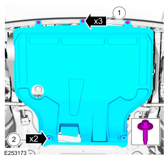
If equipped.
Remove the bolts and the underbody shield.
-
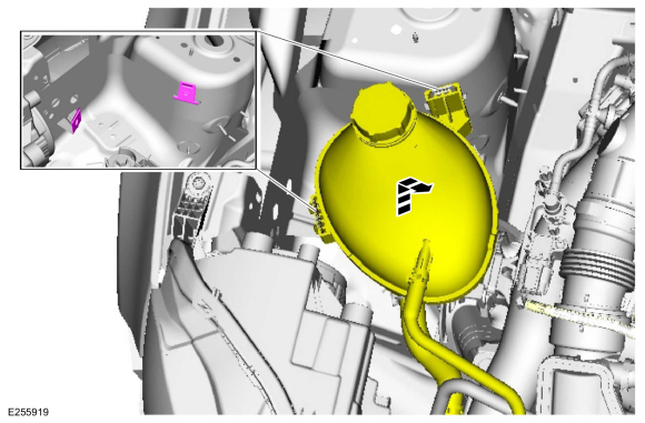
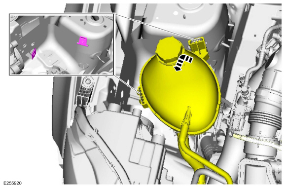
Position the degas bottle aside.
-
Remove the battery.
Refer to: Battery (414-01 Battery, Mounting and Cables, Removal and Installation).
1.5L Duratec, 1.0L GTDI and 6F15 Automatic Transmission
-
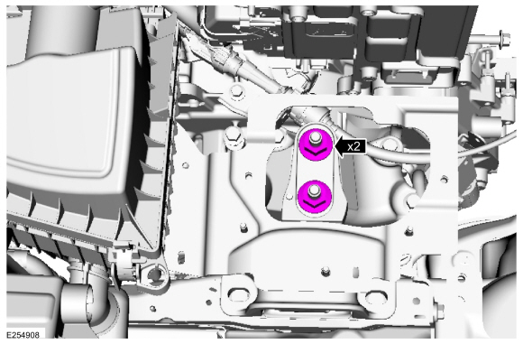
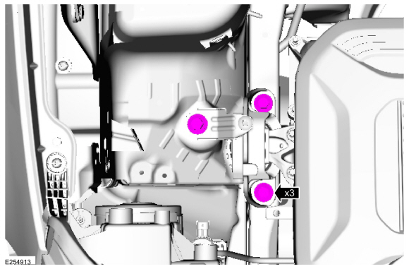
Loosen, but do not remove the transmission mounting assembly nuts.
-
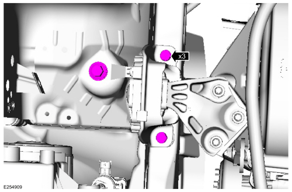
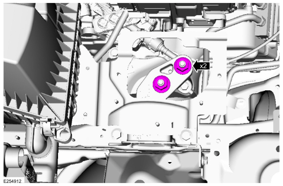
Loosen, but do not remove the engine mount bolts.
-
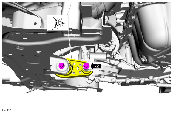
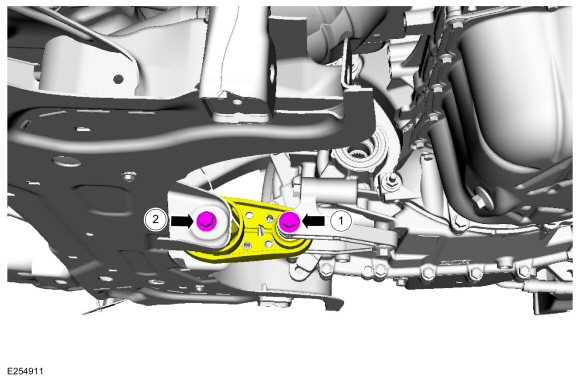
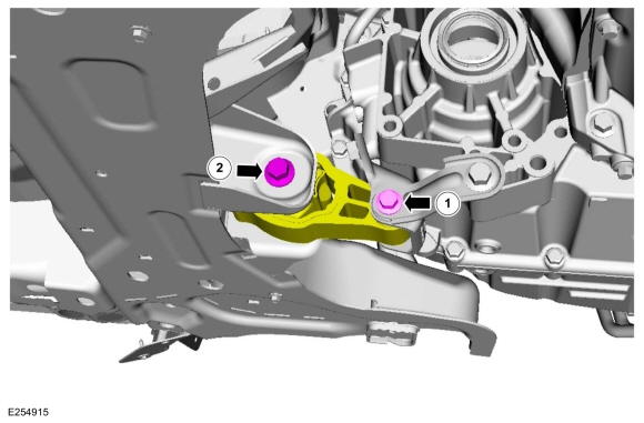
Loosen, but do not remove the 2 roll restrictor bolts. Verify that the roll restrictor is loose.
1.5L Duratec and 6F35 Automatic Transmission
-
Loosen, but do not remove the transmission mounting assembly nuts.
-
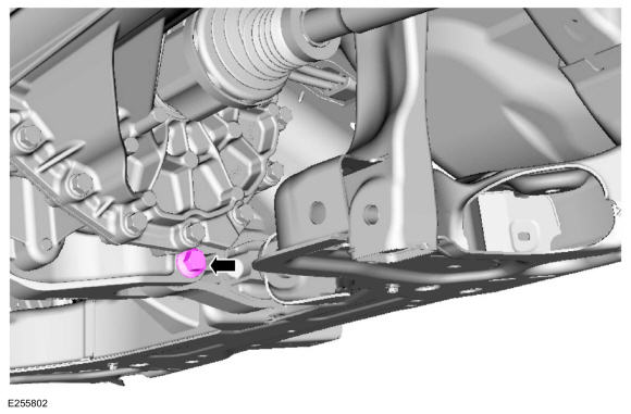
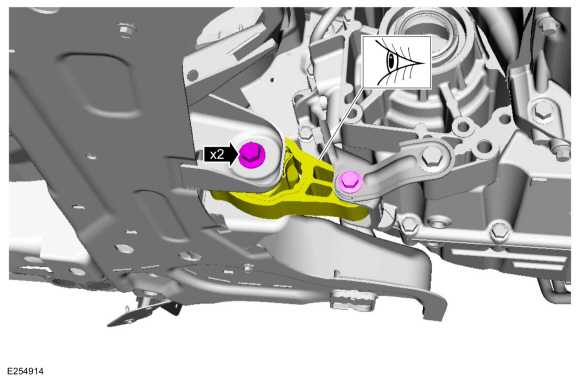
Loosen, but do not remove the engine mount bolt.
-
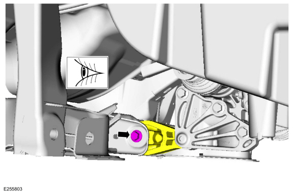
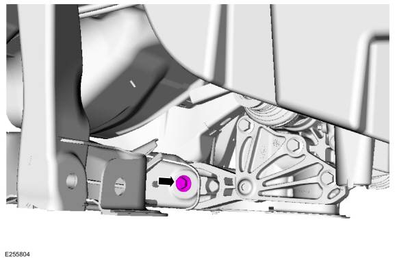
Loosen, but do not remove the roll restrictor bolt.
-
Loosen, but do not remove the roll restrictor bolt. Verify that the roll restrictor is loose.
2.0L
-
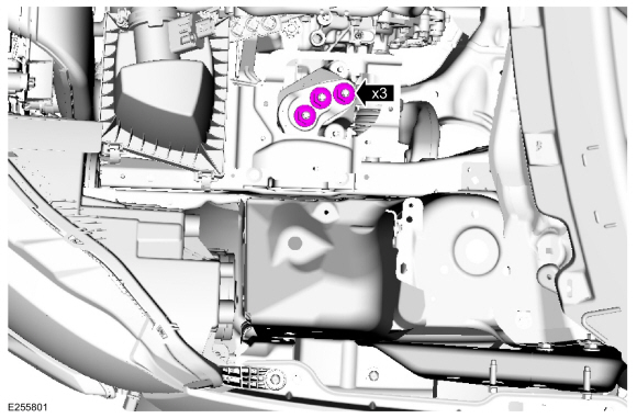
Loosen, but do not remove the transmission mounting assembly nuts.
-
Loosen, but do not remove the engine mount bolts.
-
Loosen, but do not remove the 2 roll restrictor bolts. Verify that the roll restrictor is loose.
All vehicles
-
Install the battery.
Refer to: Battery (414-01 Battery, Mounting and Cables, Removal and Installation).
-
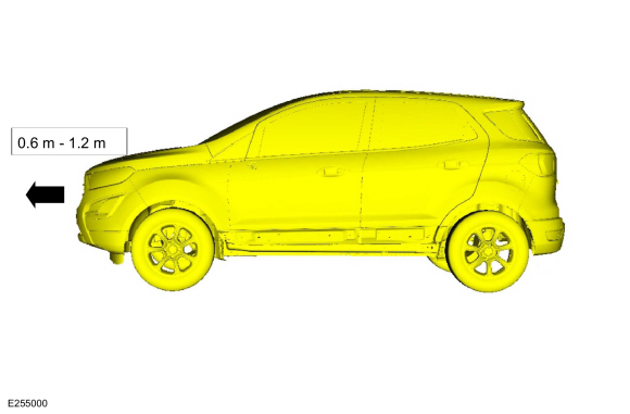
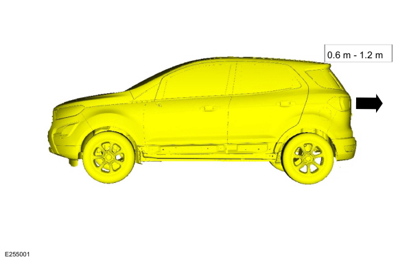
NOTE:
Do not twist or strain the powertrain/drivetrain mounts or damage to the mounts may occur.
Start the vehicle and move it forward 0.6 m (1.97 ft) - 1.2 m (3.94 ft).
-
NOTE:
Do not twist or strain the powertrain/drivetrain mounts or damage to the mounts may occur.
Move the vehicle in reverse the same distance 0.6 m (1.97 ft) - 1.2 m (3.94 ft).
-
Remove the battery.
Refer to: Battery (414-01 Battery, Mounting and Cables, Removal and Installation).
-
Raise and support the vehicle.
Refer to: Jacking and Lifting - Overview (100-02 Jacking and Lifting, Description and Operation).
1.5L Duratec, 1.0L GTDI and 6F15 Automatic Transmission
-
-
Tighten the roll restrictor bolt.
Torque:
52 lb.ft (70 Nm)
-
Tighten the roll restrictor bolt.
Torque:
81 lb.ft (110 Nm)
-
Tighten the transmission mounting assembly nuts.
Torque:
103 lb.ft (140 Nm)
-
Tighten the engine mount bolts.
Torque:
35 lb.ft (47.5 Nm)
1.5L Duratec and 6F35 Automatic Transmission
-
Tighten the roll restrictor bolt.
Torque:
81 lb.ft (110 Nm)
-
Tighten the roll restrictor bolt.
Torque:
52 lb.ft (70 Nm)
-
Tighten the engine mount bolt.
Torque:
35 lb.ft (47.5 Nm)
-
Tighten the transmission mounting assembly nuts.
Torque:
103 lb.ft (140 Nm)
2.0L
-
-
Tighten the roll restrictor bolt.
Torque:
52 lb.ft (70 Nm)
-
Tighten the roll restrictor bolt.
Torque:
85 lb.ft (115 Nm)
-
Tighten the transmission mounting assembly nuts.
Torque:
103 lb.ft (140 Nm)
-
Tighten the engine mount bolts.
Torque:
35 lb.ft (47.5 Nm)
All vehicles
-
Position back the degas bottle.
-
Install the battery.
Refer to: Battery (414-01 Battery, Mounting and Cables, Removal and Installation).
-
If equipped.
Install the underbody shield and the retainers.
-
Test the system for normal operation.
Check
NOTE:
Refer to the appropriate Section 303-01 for the specifications.
NOTE:
The cylinder bore must be within the specifications for taper and out-of-round before fitting a piston...
Special Tool(s) /
General Equipment
Plastic Scraper
Nylon Bristle Disk
Plastic Razor Blade
Lint-Free Towel
Isopropyl Alcohol – 90 Percent Minimum
Materials
Name
Specification
Motorcraft® Silicone Gasket RemoverZC-30-A, AZC-30-C
-
Motorcraft® Metal Surface Prep WipesZC-31-B
-
Motorcraft® Engin..
Other information:
Materials
Name
Specification
Motorcraft® Orange Prediluted Antifreeze/CoolantVC-3DIL-B
WSS-M97B44-D2
Motorcraft® Orange Concentrated Antifreeze/CoolantVC-3-B
WSS-M97B44-D
Removal
Drain the cooling system.
Refer to: Engine Cooling System Draining, Vacuum Filling and Bleeding
(303-03C Engine Cooling - 2.0L Duratec-HE (12..
Removal
NOTE:
LH side shown, RH side similar.
Remove the front door trim panel
Refer to: Front Door Trim Panel (501-05 Interior Trim and Ornamentation, Removal and Installation).
Remove the front door lock control switch.
Release the front door lock control switch retaining tabs.
Remove the front door lock control swit..
 General Procedures - Piston Selection
 General Procedures - RTV Sealing Surface Cleaning and Preparation