Ford Ecosport: Engine System - General Information / General Procedures - Cylinder Head Distortion
Ford Ecosport 2014-2026 Service and Repair Manual / Engine / Engine System - General Information / General Procedures - Cylinder Head Distortion
Special Tool(s) / General Equipment
| Feeler Gauge |
Check
NOTE: Refer to the appropriate Section 303-01 for the specification.
-
NOTE: Make sure all cylinder head surfaces are clear of any gasket material, silicone sealant, oil and coolant. The cylinder head surface must be clean and dry before running a flatness check.
NOTE: Use a Straightedge that is calibrated by the manufacturer to be flat within 0.005 mm (0.0002 in) per running foot of length, such as Snap-On® GA438A or equivalent. For example, if the Straightedge is 61 cm (24 in) long, the machined edge must be flat within 0.010 mm (0.0004 in) from end to end.
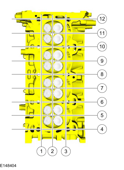
Using a Straightedge and a Feeler Gauge Set, inspect the cylinder head for flatness in the sequence shown.
Use the General Equipment: Feeler Gauge
 |
 General Procedures - Cylinder Bore Taper
Check
NOTE:
Refer to the appropriate Section 303-01 for the specification.
Measure the cylinder bore at the top, middle and bottom
of piston ring travel in 2 directions as indicated...
 General Procedures - Engine Noise Identification and Location
NOTE:
This procedure uses multiple tools/methods to help locate the
source of engine noise. It may be necessary to repeatedly compare the
sound between the tools/methods to help locate the source of the noise...
Other information:
Ford Ecosport 2014-2026 Service and Repair Manual: Removal and Installation - Front Door Check Arm
Removal NOTE: Removal steps in this procedure may contain installation details. NOTE: LH side shown, RH side similar. Open the front door. Remove the check arm bolt. Torque: 17 lb...
Ford Ecosport 2014-2026 Service and Repair Manual: Removal and Installation - Front Seat Control Switch
Removal NOTE: LHD driver seat shown, RHD driver seat similar. Remove the front seat. Refer to: Front Seat (501-10A Front Seats, Removal and Installation). Release the retainer and remove the manual lumbar handle...
Copyright © 2026 www.foecosport2.com

 WARNING:
Wear eye and ear protection when servicing a vehicle.
Failure to follow this instruction may result in serious personal
injury.