Ford Ecosport: Engine Cooling - 2.0L Duratec-HE (129kW/175PS) / General Procedures - Coolant Hose
Special Tool(s) / General Equipment
| Hose Clamp(s) | |
| Hose Clamp Remover/Installer |
Repair
 WARNING:
Always allow the engine to cool before opening the cooling
system. Do not unscrew the coolant pressure relief cap when the engine
is operating or the cooling system is hot. The cooling system is under
pressure; steam and hot liquid can come out forcefully when the cap is
loosened slightly. Failure to follow these instructions may result in
serious personal injury.
-
If necessary, drain the cooling system.
Refer to: Engine Cooling System Draining, Vacuum Filling and Bleeding (303-03C Engine Cooling - 2.0L Duratec-HE (129kW/175PS), General Procedures).
-
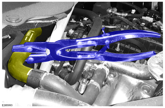
If it is necessary to limit coolant loss, pinch the
coolant hoses using hose pinch pliers. Place the hose pinch pliers far
enough from the ends so it does not stretch the hose and can completely
collapse the hose.
Use the General Equipment: Hose Clamp(s)
 |
-
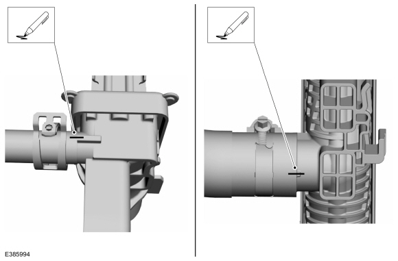
Note the hose location and routing for installation. If
removing multiple hoses, use a paint pen or pens to mark the hose ends
to their components to identify the correct routing and position during
installation. Take pictures as needed to help clarify the correct hose
routing and position during installation. Note the location and position
of all retainers and fasteners and routing guides on the hose for
installation.
 |
-
NOTE: Worm gear clamps can be fastened to the hose to maintain position for assembly and service.
If equipped with worm gear clamps, loosen the worm gear clamps. If the clamp is not fastened to the hose, note the position of the clamp on the hose. Position the clamp as needed to allow the hose to clear any barb or rib on the component that it is connected to.
 |
-
NOTE: Some constant tension clamps have a lock feature that will hold the clamp in the open position. The lock feature is engaged when the clamp is opened or compressed a certain distance.
NOTE: Constant tension clamps can be fastened to the hose to maintain position for assembly and service.
If equipped with constant tension clamps, compress the constant tension clamps. If equipped, compress the clamp to lock the clamp in the open position. If the clamp is not fastened to the hose, note the position of the clamp on the hose. Position the clamp as needed to allow the hose to clear any barb or rib on the component that it is connected to.
Use the General Equipment: Hose Clamp Remover/Installer
 |
-
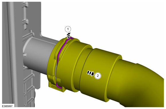
NOTE: Spring clip retainers have a feature to hold the spring clip in the released position. The metal spring will rest in a detent molded into the plastic end of the hose.
If equipped with a spring clip retainer, pull the hose spring clip out until the end of the clip is in the detent on the hose end and disconnect the hose.
 |
-
For hoses with quick release couplings, release the
retainer feature on the coupling and remove the hose from the component.
Twist the hose as needed to free the hose from the component and remove
the hose from the component.
Refer to: Quick Release Coupling (310-00I) .
-
For hoses with constant tension clamps or worm gear
clamps, it might be necessary to use a hose removal hook to break the
hose loose from the component. Carefully work the removal hook around
the diameter of the component while twisting the hose to free the hose
from the component. If a new hose is being installed, pliers or channel
locks can be used to twist the hose using care not to damage the
component.
-
Remove or release all retainers or fasteners. Release
the hose or hoses from all routing guides. Remove the hose or hoses.
-
Route the hose in the same location and position noted
during removal. Install the fasteners and retainers in the same
locations as noted during removal.
-
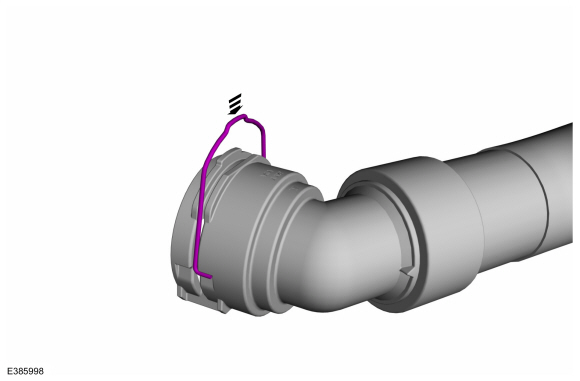
If equipped with a spring clip retainer, push the spring clip retainer inward to the installed position.
 |
-
If necessary for quick release couplings, reset the retainer feature.
Refer to: Quick Release Coupling (310-00I) .
-
Lubricate the hose and the component with clean coolant.
Install the hose on the component. For hoses with spring clip retainers
or quick release couplings, listen for an audible click to indicate the
hose is fastened completely.
Refer to: Specifications (303-03C Engine Cooling - 2.0L Duratec-HE (129kW/175PS), Specifications).
-
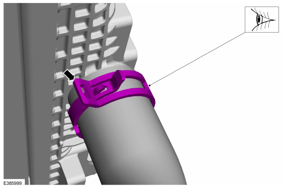
If equipped with constant tension clamps, compress the
constant tension clamps and position the clamps in the same location and
position as noted during removal and release the clamp. If equipped
with a feature to hold the clamp open, use a screwdriver to release the
lock feature. Compress and adjust the clamp as needed to align it as
noted during removal.
Use the General Equipment: Hose Clamp Remover/Installer
 |
-
If equipped with worm gear clamps, position the clamps
in the same location and position as noted during removal and tighten
the clamps.
Torque: 44 lb.in (5 Nm)
 |
-
Fill and bleed the cooling system.
Refer to: Engine Cooling System Draining, Vacuum Filling and Bleeding (303-03C Engine Cooling - 2.0L Duratec-HE (129kW/175PS), General Procedures).
 Diagnosis and Testing - Engine Temperature
Diagnostic Trouble Code (DTC) Chart
Diagnostics in this manual assume a certain skill level and knowledge of Ford-specific diagnostic practices. REFER to: Diagnostic Methods (100-00 General Information, Description and Operation)...
 General Procedures - Engine Cooling System Draining, Vacuum Filling and Bleeding
Special Tool(s) /
General Equipment
ROB75240Coolant/Battery Refractometer (Fahrenheit)
Fluid Container
Cooling System Vacuum Tester and Refiller
Materials
Name
Specification
Motorcraft® Orange Prediluted Antifreeze/CoolantVC-3DIL-B
WSS-M97B44-D2
Motorcraft® Orange Concentrated Antifreeze/CoolantVC-3-B
WSS-M97B44-D
..
Other information:
Ford Ecosport 2014-2025 Service and Repair Manual: Removal and Installation - Throttle Body
Removal NOTICE: The turbocharger compressor vanes can be damaged by even the smallest particles. When removing any turbocharger or engine air intake system component, ensure that no debris enters the system. Failure to do so may result in damage to the turbocharger. If equipped, remove the engine appearance cover. Re..
Ford Ecosport 2014-2025 Service and Repair Manual: Removal and Installation - Rocker Panel Inner Reinforcement
Special Tool(s) / General Equipment Resistance Spotwelding Equipment Grinder Belt Sander 8 mm Drill Bit MIG/MAG Welding Equipment Spot Weld Drill Bit Locking Pliers Removal NOTE: The rocker panel inner reinforcement is made of DP (Dual Phase) 800 steel and cannot be sectioned. It must be removed at factory seams. ..

 WARNING:
Wear eye and ear protection when servicing a vehicle.
Failure to follow this instruction may result in serious personal
injury.