Ford Ecosport: Engine Cooling - 2.0L Duratec-HE (129kW/175PS) / Diagnosis and Testing - Engine Temperature
Diagnostic Trouble Code (DTC) Chart
Diagnostics in this manual assume a certain skill level and knowledge of Ford-specific diagnostic practices.
REFER to: Diagnostic Methods (100-00 General Information, Description and Operation).
| Module | DTC | Description | Action |
|---|---|---|---|
| PCM | P0116:00 | Engine Coolant Temperature Sensor 1 Circuit Range/Performance: No Sub Type Information | GO to Pinpoint Test DL |
| PCM | P0117:00 | Engine Coolant Temperature Sensor 1 Circuit Low: No Sub Type Information | GO to Pinpoint Test DX |
| PCM | P0118:00 | Engine Coolant Temperature Sensor 1 Circuit High: No Sub Type Information | GO to Pinpoint Test DX |
| PCM | P0125:00 | Insufficient Coolant Temp For Closed Loop Fuel Control: No Sub Type Information | GO to Pinpoint Test DL |
| PCM | P0128:00 | Coolant Thermostat (Coolant Temp Below Thermostat Regulating Temperature): No Sub Type Information | GO to Pinpoint Test DL |
| PCM | P1022:00 | Cylinder Head Temperature Sensor 2 Circuit Low: No Sub Type Information | GO to Pinpoint Test DL |
| PCM | P1023:00 | Cylinder Head Temperature Sensor 2 Circuit High: No Sub Type Information | GO to Pinpoint Test DL |
| PCM | P1025:00 | Cylinder Head Temperature Sensor 2 Out Of Self Test Range: No Sub Type Information | GO to Pinpoint Test DL |
| PCM | P1026:00 | Engine Coolant Temperature 1 / Cylinder Head Temperature 2 Correlation: No Sub Type Information | GO to Pinpoint Test DL |
| PCM | P1116:00 | Engine Coolant Temperature Sensor Out Of Self Test Range: No Sub Type Information | GO to Pinpoint Test DX |
| PCM | P1285:00 | Cylinder Head Overtemperature Condition: No Sub Type Information | GO to Pinpoint Test DL |
| PCM | P1299:00 | Cylinder Head Overtemperature Protection Active: No Sub Type Information | GO to Pinpoint Test DL |
Global Customer Symptom Code (GCSC) Chart
Diagnostics in this manual assume a certain skill level and knowledge of Ford-specific diagnostic practices.
REFER to: Diagnostic Methods (100-00 General Information, Description and Operation).
| Symptom | Action |
|---|---|
| Start/Run/Move > Starting > Hard Start/Long Crank > Always | GO to Pinpoint Test DL |
| Start/Run/Move > Running > Smoke From Exhaust > Black | GO to Pinpoint Test DX |
| Driving Performance > Runs Rough > All Running Modes > Always | GO to Pinpoint Test DL |
| Driving Performance > Idle Quality > Rough > Always | GO to Pinpoint Test DX |
| Driving Performance > Poor Fuel Economy > Combined > Loaded | GO to Pinpoint Test DX |
Pinpoint Tests


 Introduction Introduction
Refer to Wiring Diagrams Cell 022 for schematic and connector information. Normal Operation and Fault Conditions On applications that do not use an ECT sensor, the CHT sensor is used to determine the engine coolant temperature. To cover the entire temperature range of both the CHT and ECT sensors, the PCM has a dual switching resistor circuit on the CHT input. A graph showing the temperature switching from the COLD END line to the HOT END line, with increasing temperature and back with decreasing temperature is included. Note the temperature to voltage overlap zone. Within this zone it is possible to have either a COLD END or HOT END value at the same temperature. For example, at 90C (194F) the voltage could read either 0.60 volt or 3.71 volts. Refer to the table for the expected values. Voltage values calculated for VREF = 5 volts. These values can vary by 15% due to sensor and VREF variations. Refer to the DTC Fault Trigger Conditions. DTC Fault Trigger Conditions
Possible Sources
|
 Introduction
| Introduction
NOTE: Engine coolant temperature must be greater than 10°C (50°F) to pass the KOEO self-test and greater than 82°C (180°F) to pass the KOER self-test. Refer to Wiring Diagrams Cell 022 for schematic and connector information. Normal Operation and Fault Conditions Refer to the DTC Fault Trigger Conditions. Voltage values calculated for VREF equals 5 volts. These values may vary by 15% due to sensor and VREF variations. 
DTC Fault Trigger Conditions
Possible Sources
|

 General Procedures - Coolant Hose
Special Tool(s) /
General Equipment
Hose Clamp(s)
Hose Clamp Remover/Installer
Repair
WARNING:
Always allow the engine to cool before opening the cooling
system...
Other information:
Ford Ecosport 2014-2025 Service and Repair Manual: Diagnosis and Testing - Airbag Supplemental Restraint System (SRS) - Vehicles With: Rear Seat Side Airbag
DTC Chart: Restraint Control Module (RCM) Diagnostics in this manual assume a certain skill level and knowledge of Ford-specific diagnostic practices. REFER to: Diagnostic Methods (100-00 General Information, Description and Operation). NOTE: Unlisted Diagnostic Trouble Codes (DTCs) are often retrieved as a result of incorrect repair procedures...
Ford Ecosport 2014-2025 Service and Repair Manual: Removal and Installation - Roof Opening Panel Frame
Removal NOTE: Removal steps in this procedure may contain installation details. Remove the headliner. Refer to: Headliner (501-05 Interior Trim and Ornamentation, Removal and Installation). Disconnect the roof opening panel motor electrical connector...
Categories
- Manuals Home
- 2nd Gen Ford Ecosport Service Manual (2014 - 2025)
- Removal and Installation - Starter Motor
- Diagnosis and Testing - Evaporative Emissions
- Removal and Installation - Fuel Pump and Sender Unit
- Description and Operation - Evaporative Emissions - System Operation and Component Description
- Diagnosis and Testing - Body Control Module (BCM)
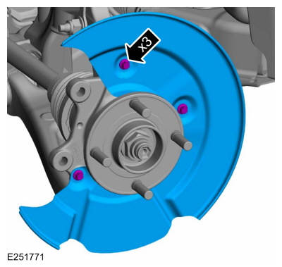
Removal and Installation - Brake Disc Shield
Removal
NOTE: Removal steps in this procedure may contain installation details.
Remove the brake disc.Refer to: Brake Disc (206-03 Front Disc Brake, Removal and Installation).
Remove the bolts and brake disc.
Torque: 80 lb.in (9 Nm)