Ford Ecosport: Rear Suspension - AWD / Disassembly and Assembly - Rear Shock Absorber
Materials
| Name | Specification |
|---|---|
| Grease - Silicone | ESA-M1C200-A |
DISASSEMBLY
NOTICE: Suspension fasteners are critical parts that affect the performance of vital components and systems. Failure of these fasteners may result in major service expense. Use the same or equivalent parts if replacement is necessary. Do not use a replacement part of lesser quality or substitute design. Tighten fasteners as specified.
NOTE: Disassembly steps in this procedure may contain assembly details.
NOTE: Typical assembly shown. actual application may vary.
-
Remove the rear shock absorber.
Refer to: Rear Shock Absorber (204-02B Rear Suspension - AWD, Removal and Installation).
-
-
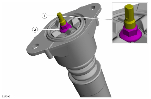
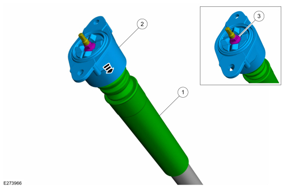
NOTICE: Do not use an impact wrench on the rear shock absorber inner rod nut.
NOTE: Use the hex-holding feature to prevent the shock absorber inner rod from rotating while removing and installing the shock absorber nut.
Lock the rear shock absorber inner rod.
-
Remove the rear shock absorber nut.
-
 |
-
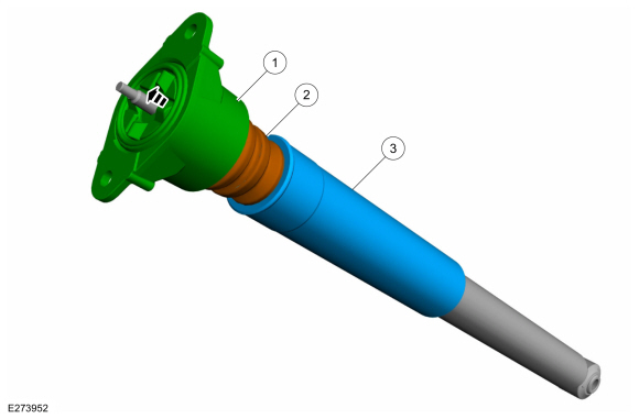
NOTICE: Do not use an impact wrench on the rear shock absorber inner rod nut.
NOTE: Note the position of the components before disassembly.
-
Remove the shock absorber top mount.
-
Remove the jounce bumper.
-
Remove the dust shield.
-
Remove the shock absorber top mount.
 |
-
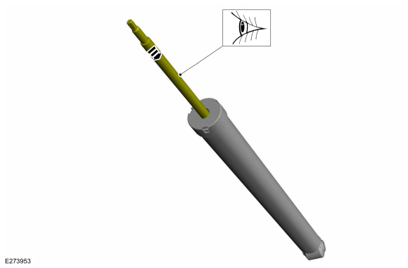
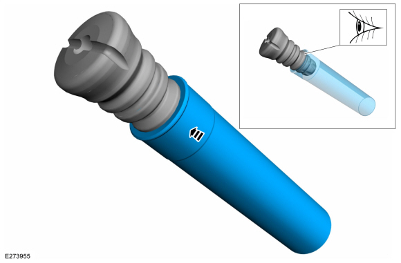
Inspect the shock absorber inner rod and push the rod into cyliner.
 |
ASSEMBLY
NOTE: Make sure that the components are installed to the position noted before removal.
-
To assemble, reverse the disassembly procedure.
-
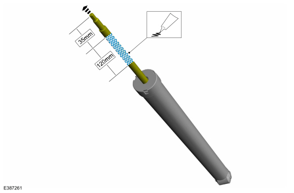
NOTICE: Take extra care not to damage the piston rod surface.
NOTE: Make sure the grease is applied completely around the shock absorber inner rod. Do not allow grease to make contact with the shock absorber rod threads.
NOTE: Avoid excess grease application to eliminate below anticipated issues.
- Customer may misinterpret excess grease seepage as oil leak from damper (Psudo leak).
- This excess grease seepage will leads to dust accumulation, results in piston rod scoring mark, seal damage and oil leak.
Material: Grease - Silicone (ESA-M1C200-A)
 |
-
NOTICE: Make sure the components are correctly aligned during assembly.
Assemble the dust shield into jounce bumper.
 |
-
-
Install the jounce bumper and dust shield assembly.
-
Install the shock absorber top mount.
-
NOTICE: Do not use an impact wrench on the rear shock absorber inner rod nut.
NOTE: Utilize the hex holding feature to prevent the shock absorber inner rod from turning while installing the shock absorber inner rod nut.
Install and tighten the new rear shock absorber nut.
Torque: 159 lb.in (18 Nm)
-
Install the jounce bumper and dust shield assembly.
 |
-
Install the rear shock absorber.
Refer to: Rear Shock Absorber (204-02B Rear Suspension - AWD, Removal and Installation).
 Removal and Installation - Wheel Knuckle - Vehicles With: Rear Disc Brakes
Special Tool(s) /
General Equipment
204-161
(T97P-1175-A)
Installer, HalfshaftTKIT-1997-LM2TKIT-1997-F/FM2TKIT-1997-FLM2
205-D070
(D93P-1175-B)
Remover, Front Wheel Hub
Tie Rod End Remover
Removal
NOTICE:
Suspension fasteners are critical parts that affect the
performance of vital components and systems...

Other information:
Ford Ecosport 2014-2025 Service and Repair Manual: General Procedures - Oil Leak Inspection
NOTE: If an overnight drive is done, the fan air or road air blast can cause erroneous readings. NOTE: When diagnosing engine oil leaks, the source and location of the leak must be positively identified prior to repair. Prior to carrying out this procedure, clean the cylinder block, cylinder heads, valve covers, oil pan and flywheel/flexplate with a suitable solvent t..
Ford Ecosport 2014-2025 Service and Repair Manual: Removal and Installation - Tailgate Release Handle
Removal NOTE: Removal steps in this procedure may contain installation details. Remove the tailgate latch. Refer to: Tailgate Latch (501-14 Handles, Locks, Latches and Entry Systems, Removal and Installation). Remove the tailgate release handle. Release the tailgate release handle. Remove the tailgate release handle. ..
Categories
- Manuals Home
- 2nd Gen Ford Ecosport Service Manual (2014 - 2025)
- Climate Control System - General Information
- Description and Operation - Evaporative Emissions - System Operation and Component Description
- Removal and Installation - Front Seat
- Removal and Installation - Fuel Pump and Sender Unit
- Removal and Installation - Catalytic Converter
Removal and Installation - Brake Disc Shield
Removal
NOTE: Removal steps in this procedure may contain installation details.
Remove the brake disc.Refer to: Brake Disc (206-03 Front Disc Brake, Removal and Installation).
Remove the bolts and brake disc.
Torque: 80 lb.in (9 Nm)