Ford Ecosport: Parking Aid - Vehicles With: Parking Aid Camera / Description and Operation - Parking Aid - System Operation and Component Description
System Operation
Rear Parking Aid Camera
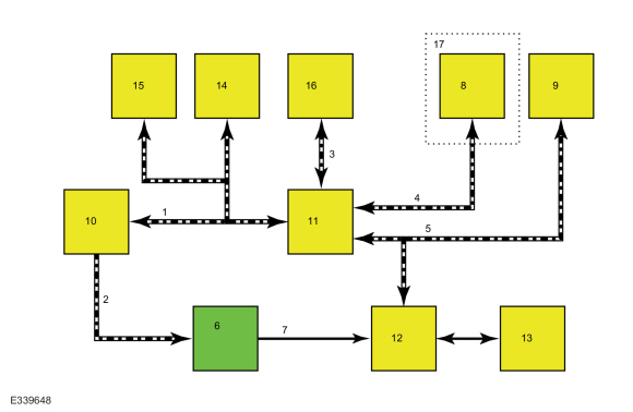
System Diagram

| Item | Description |
|---|---|
| 1 | HS-CAN1 |
| 2 | LIN |
| 3 | HS-CAN2 |
| 4 | MS-CAN |
| 5 | HS-CAN3 |
| 6 | Rear Parking Aid Camera |
| 7 | video signal |
| 8 | TRM |
| 9 | IPC |
| 10 | BCM |
| 11 | GWM |
| 12 | ACM |
| 13 | FDIM |
| 14 | PAM |
| 15 | PCM |
| 16 | PSCM |
| 17 | Trailer Tow |
Network Message Chart
BCM Network Input Messages
| Broadcast Message | Originating Module | Message Purpose |
|---|---|---|
| Camera status | IPC | Used to command the visual park aid alert, static guidelines, active guidelines and zoom level. |
| Gear lever position | PCM | Used to enable the rear parking aid camera display when reverse gear is selected. |
| Parking aid range to object | PAM | Used to highlight the zone on the video image where an object has been detected by the rear parking aid system. |
| Steering pinion angle | PSCM | Used to generate the active guidelines on the video display (if equipped with active guidelines). |
| Trailer lamp connection | TRM | Used to disable the fixed and active guidelines when a trailer is attached to the vehicle. |
| Vehicle speed | PCM | Used to support the rear parking aid camera delay feature. |
ACM Network Input Messages
| Broadcast Message | Originating Module | Message Purpose |
|---|---|---|
| Gear lever position | PCM | Used to enable the rear parking aid camera display when reverse gear is selected. |
IPC Network Input Messages
| Broadcast Message | Originating Module | Message Purpose |
|---|---|---|
| Camera settings | BCM | Used to command the visual park aid alert, static guidelines, active guidelines and zoom level. |
Rear Parking Aid Camera
NOTE: The liftgate must be fully closed for correct operation of the rear parking aid camera system.
The rear parking aid camera image is displayed by the FDIM when the transmission is placed in reverse. To determine the selector lever position and enable the rear parking aid camera display, the PCM sends the gear position message to BCM and the ACM . The rear parking aid camera generates a video signal any time it receives voltage, regardless of the current configuration. If the rear parking aid camera is not configured properly, some features may be inoperative. The rear parking aid camera is supplied voltage when the ignition is on. When the rear parking aid camera is on, the image signal is sent from the rear parking aid camera on shielded twisted pair wires to the ACM , which displays the image on the FDIM .
The following rear parking aid camera system features are driver selectable:
- Visual park aid alert — assists the driver to visually see the object causing the parking aid system to sound.
- Manual zoom — allows the driver to manually zoom closer to an object behind the vehicle.
- Video delay — allows the driver to see the image behind the vehicle after the vehicle is shifted out of reverse. The image is not displayed if the vehicle is shifted into park.
The following rear parking aid camera system features are not driver selectable:
- Fixed guidelines — assists the driver with backing into a parking space or aligning the vehicle with an object.
- Active guidelines — projects the intended path of the vehicle based on steering wheel input.
The FDIM settings menu is used to turn the visual park aid alert and video delay on and off. The visual park aid alert and video delay features are generated and controlled by the ACM .
To turn the manual zoom feature on and off, the driver uses an on screen button located on the FDIM while in reverse. The driver generated commands originate at the FDIM , which is hardwired to the ACM . The ACM sends the driver generated commands to the BCM . The BCM sends the command to the rear parking aid camera via the LIN . The zoom is generated by the rear parking aid camera on top of the video image that is sent to the ACM .
The fixed and active guidelines are generated by the rear parking aid camera and are not selectable by the driver.
LIN Communication
The LIN is a dedicated single wire communication network. The LIN circuit is used between the rear parking aid camera and the BCM . The modules use broadcast serial communication over the LIN , with the BCM sending a message, and the rear parking aid camera either replying to or simply receiving certain messages. The BCM is the master module on the LIN , and it sets and stores Diagnostic Trouble Codes (DTCs) for the rear parking aid camera and the communication network.
The messages sent from the BCM to the rear parking aid camera are:
- Liftgate ajar status
- Camera configuration data
- Manual zoom request
- Enable/disable visual park aid alert
- Enable/disable fixed guidelines
- Enable/disable active guidelines
- Parking aid audible warning status
- Parking aid sensor distance to object data
- Steering wheel angle data
The reply messages sent from the rear parking aid camera to the BCM are:
- Camera status
- Zoom status
- Visual park aid alert status
- Fixed guideline status
- Active guideline status
- Camera part number data
Visual Park Aid Alert
NOTE: The on-screen alert color transitions may not match changes in the audible parking aid alert tone frequency.
The visual park aid alert feature displays a visual highlight in the zone where an object has been detected by the parking aid system. This feature utilizes the parking aid sensor data from the PAM to generate the visual highlights on the video image. When reverse gear is selected and an object is detected by a rear parking aid sensor, the parking aid range to object data message from the PAM is used by the ACM to generate the alert.
If the visual park aid alert feature is enabled, the feature is still operational even if the rear parking aid system has been disabled by the driver.
Fixed Guidelines
NOTE: The color-coded lines cannot indicate accurate or consistent distances between the rear of the vehicle and objects shown in the video image. This normal condition is due to variances in vehicle ride height, including, but not limited to, vehicle loading.
The rear parking aid camera fixed guidelines feature displays guidelines on top of the video image to assist the driver with alignment of the vehicle. A dashed line on the displayed image represents the center of the vehicle and 3 color-coded lines (red, yellow, green) identify different zones between the rear of the vehicle and objects.
Fixed guidelines are not shown when the liftgate is open.
If the vehicle is equipped with a factory TRM , the fixed guidelines are not shown when a trailer is electrically connected to the vehicle.
If the video image is manually zoomed by the driver, only the dashed center line is displayed on the image.
Active Guidelines
The rear parking aid camera active guidelines feature displays guidelines on top of the video image to assist the driver with maneuvering a vehicle into a space. The guidelines display the expected path of vehicle travel based on the current steering angle.
The rear parking aid camera active guidelines feature displays dynamic guidelines that correspond to the projected path of the vehicle travel based on the current steering angle. Several modules are involved in generating the steering angle data used to support the active guidelines. The PSCM generates the steering angle message that is sent to the BCM , with the GWM acting as the gateway. The BCM then sends the steering angle data to the rear parking aid camera via the LIN circuit. The camera uses this data to generate the active guidelines over the video image.
Active guidelines are not shown when the liftgate is open.
If the steering wheel is in the straight-ahead position the active guidelines are not shown.
If the vehicle is equipped with a factory TRM , the active guidelines are not shown when a trailer is electrically connected to the vehicle.
Manual Zoom
The manual zoom feature is controlled by the rear parking aid camera. The feature is only available when the transmission selector is in reverse. When the driver manually zooms the rear parking aid camera image, the zoom command message is sent from the ACM to the BCM , to the rear parking aid camera via the LIN circuit. The rear parking aid camera then zooms the image to the requested level.
If the manual zoom feature is enabled and the vehicle is shifted out of reverse, the manual zoom feature is disabled. The manual zoom feature must be re-enabled the next time the vehicle is shifted into reverse.
Video Delay
When the video delay is turned on, the video image remains displayed after the transmission is shifted out of reverse until the vehicle reaches 10 km/h (6 mph). With the delay off (default), the image displays until the transmission is shifted out of reverse. The delay feature is controlled by the ACM .
Component Description
Rear Parking Aid Camera
The rear parking aid camera is located on the rear bumper. The rear parking aid camera provides a video signal any time it receives voltage and ground, regardless of configuration.
The rear parking aid camera communicates with the BCM through a LIN circuit.
The rear parking aid camera must be configured after replacement in order for all features to operate properly. To configure the rear parking aid camera, place the ignition ON and leave on for 5 minutes to allow the automatic BCM /camera flash operation to complete.
FDIM
The rear parking aid camera image can be displayed by the FDIM . For additional information about the displays, Refer to the appropriate section in Group 415 for the procedure.
BCM
NOTE: The BCM settings and configuration have no influence over the video signal from the rear parking aid camera. The rear parking aid camera provides a video signal any time it receives voltage and ground.
The BCM serves as a gateway module between the rear parking aid camera and other modules on the HS-CAN1 , HS-CAN2 and MS-CAN . It communicates with the rear parking aid camera via the LIN and stores Diagnostic Trouble Codes (DTCs) for the rear parking aid camera and the LIN in the event of a concern.
The BCM requires PMI when replaced.
Refer to: Module
Configuration - System Operation and Component Description (418-01
Module Configuration, Description and Operation).
 Description and Operation - Parking Aid - Overview
Overview
The
rear parking aid camera system visually aids the driver while reversing
or reverse parking the vehicle. When reverse gear is selected, the rear
parking aid camera image is displayed on FDIM
...
 Diagnosis and Testing - Parking Aid
Diagnostic Trouble Code (DTC) Chart
Diagnostics in this manual assume a certain skill level and knowledge of Ford-specific diagnostic practices. REFER to: Diagnostic Methods (100-00 General Information, Description and Operation)...
Other information:
Ford Ecosport 2014-2026 Service and Repair Manual: Removal and Installation - High Mounted Stoplamp
Removal NOTICE: Washer fluid may escape. Release the clips and remove the high mounted stop lamp. Disconnect the electrical connector. Installation To install, reverse the removal procedure...
Ford Ecosport 2014-2026 Service and Repair Manual: Removal and Installation - Halfshaft Seal RH - AWD
Special Tool(s) / General Equipment 205-153 (T80T-4000-W) Handle 307-718Installer, Axle SealTKIT-2013B-FLTKIT-2013B-ROW 307-718-01Adaper, 307-718 Puller Punch Removal Remove the transfer case assembly...
Categories
- Manuals Home
- 2nd Gen Ford Ecosport Service Manual (2014 - 2026)
- Removal and Installation - Body Control Module (BCM)
- Removal and Installation - Front Seat
- Diagnosis and Testing - Evaporative Emissions
- Description and Operation - Evaporative Emissions - System Operation and Component Description
- Diagnosis and Testing - Body Control Module (BCM)
Removal and Installation - Front Stabilizer Bar
Special Tool(s) / General Equipment
Tie Rod End Remover Transmission JackRemoval
NOTICE: Suspension fasteners are critical parts that affect the performance of vital components and systems. Failure of these fasteners may result in major service expense. Use the same or equivalent parts if replacement is necessary. Do not use a replacement part of lesser quality or substitute design. Tighten fasteners as specified.
NOTE: Removal steps in this procedure may contain installation details.
NOTICE: Disconnect the b