Ford Ecosport: Automatic Transmission - 6-Speed Automatic Transmission – 6F35 / Description and Operation - Low/Reverse Clutch Assembly
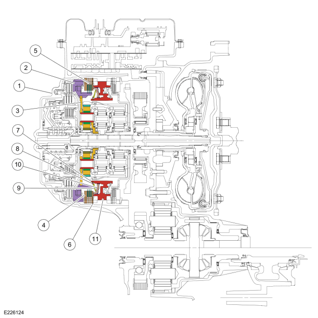
Low/Reverse Clutch Exploded View

| Item | Description |
| 1 | Transmission case |
| 2 | Low One-Way Clutch (OWC) |
| 3 | Rear planetary carrier |
| 4 | Low/reverse clutch pressure plate |
| 5 | Low/reverse clutch |
| 6 | Low/reverse clutch wave spring |
| 7 | Low/reverse clutch piston return spring snap ring |
| 8 | Low/reverse clutch piston return spring snap ring retainer |
| 9 | Low/reverse clutch piston return spring |
| 10 | Low/reverse clutch piston |
| 11 | Center support |
Low/Reverse Clutch Cutaway View
Low/Reverse Clutch Mechanical Operation
The low/reverse clutch is a brake clutch that holds the low One-Way Clutch (OWC) which is splined to the rear planetary carrier. The low/reverse clutch is applied in manual LOW, REVERSE and 1st gear up to 8 km/h (5 mph).
Hydraulic pressure from the regulator valve in the valve body pushes the low/reverse clutch piston against the low/reverse clutch pack to apply the clutch. The rear planetary carrier is held stationary to the transmission case as a result of the clutch being applied.
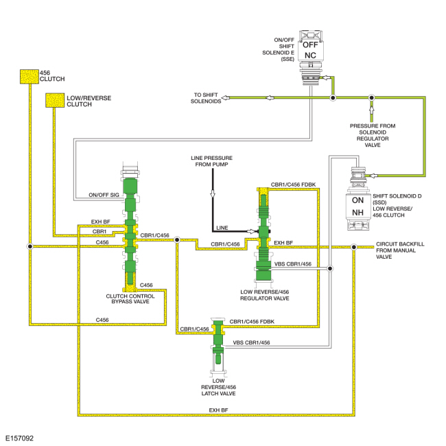
Low/Reverse Clutch Hydraulic Circuits (Applied in REVERSE)
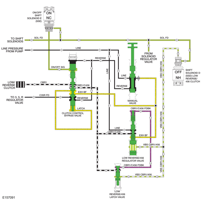
Line pressure is supplied to the low reverse/456 regulator valve by the pump in every gear and manual lever position. To apply the low/reverse clutch, SSD supplies varying solenoid pressure to the low reverse/456 regulator and latch valves. As the low reverse/456 regulator valve moves, it supplies the clutch control bypass valve and low reverse/456 latch valve with regulated line pressure through the CBR1/C456 circuit. The low reverse/456 latch valve directs the regulated line pressure to the opposite side of the 456 regulator valve through the CBR1/C456 FDBK circuit for gradual low reverse/456 clutch engagement. The low/reverse clutch is applied in PARK, REVERSE, NEUTRAL, 1st gear below 8 km/h (5 mph) and manual LOW position.
In REVERSE, both solenoid pressure from ON/OFF SSE and line pressure from the manual valve in the REVERSE circuit apply pressure to the clutch control bypass valve to position it for low/reverse clutch application. Regulated line pressure from the CBR1/C456 circuit is directed to the low/reverse clutch by the clutch control bypass valve through the CBR1 circuit to apply the low/reverse clutch.
Low/Reverse Clutch Hydraulic Circuits (Applied in PARK, NEUTRAL, LOW or 1st gear below 8 km/h [5 mph])
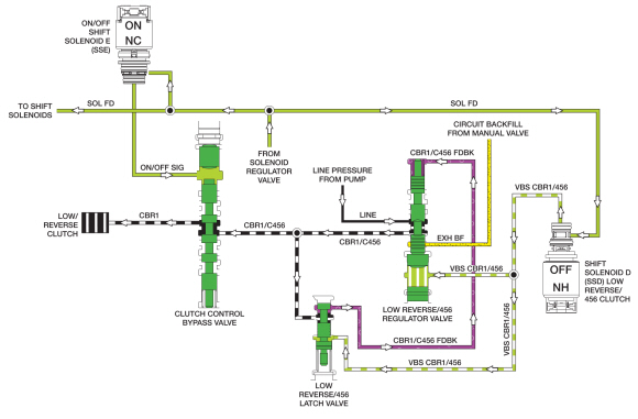
When the low/reverse clutch is applied in PARK, NEUTRAL, LOW or 1st gear below 8 km/h (5 mph), only pressure from ON/OFF SSE , positions the clutch control bypass valve. Line pressure from the REVERSE circuit is not supplied by the manual valve.
Low/Reverse Clutch Hydraulic Circuits (Released)
When the low/reverse clutch is released in 1st gear above 8 km/h (5 mph), 2nd and 3rd gears, solenoid pressure from SSD is removed from the low reverse/456 regulator and latch valves which positions the valves to block line pressure and release the low/reverse clutch. Solenoid pressure from SSE is removed from the clutch control bypass valve to position it to apply the overdrive (4, 5, 6) clutch.
When the low/reverse clutch is released in 1st gear above 8 km/h (5 mph), 2nd and 3rd gears, exhaust backfill supplied to the low reverse/456 clutch regulator valve and the clutch control bypass valve by the manual valve through the EXH BF circuit is directed to the low reverse/456 latch valve, low/reverse clutch and overdrive (4, 5, 6) clutch to fill the unused circuits with unpressurized transmission fluid.
When the low/reverse clutch is released in 4th, 5th and 6th gears, the low reverse/456 regulator valve supplies regulated pressure to the clutch control bypass valve through the CBR1/C456 circuit. With ON/OFF SSE in the OFF position, the regulated pressure is directed to the overdrive (4, 5, 6) clutch.
For details on valve body hydraulic circuits and solenoid operation.
For
additional information, refer to: Transmission Description (307-01B
Automatic Transmission - 6-Speed Automatic Transmission – 6F35,
Description and Operation).

 Description and Operation - Overdrive Clutch Assembly
Overdrive (O/D) (4, 5, 6) Clutch Exploded View
Item
Description
1
Direct/overdrive clutch hub assembly
2
Overdrive clutch piston inner seal
3
Input shaft
4
Overdrive clutch piston outer seals
5
Overdrive clutch piston
..
Other information:
Ford Ecosport 2014-2025 Service and Repair Manual: Description and Operation - External Controls - Component Location
6F15 Item Description 1 Selector lever knob 2 Selector lever bezel 3 Brake shift interlock actuator 4 Selector lever cable adjuster 5 Selector lever cable 6 Selector lever assembly 7 SelectShift® switch (if equipped) 6F35 Item Description 1 Selector lever knob ..
Ford Ecosport 2014-2025 Service and Repair Manual: Removal and Installation - Steering Gear Boot
Special Tool(s) / General Equipment 204-169Clamping Tool, Boot Retaining Clamp Removal NOTE: Removal steps in this procedure may contain installation details. Remove the tie rod end. Refer to: Tie Rod End (211-02 Power Steering, Removal and Installation). Remove the tie rod end jamb nut. ..
Categories
- Manuals Home
- 2nd Gen Ford Ecosport Service Manual (2014 - 2025)
- Removal and Installation - Starter Motor
- Diagnosis and Testing - Evaporative Emissions
- Removal and Installation - Evaporative Emission Canister Purge Valve
- Description and Operation - Evaporative Emissions - System Operation and Component Description
- General Procedures - Transmission Fluid Level Check
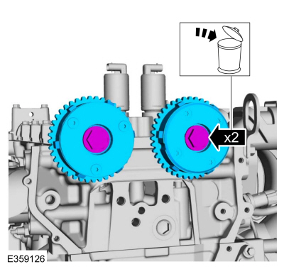
Removal and Installation - Variable Camshaft Timing (VCT) Unit
Removal
NOTICE: During engine repair procedures, cleanliness is extremely important. Any foreign material, including any material created while cleaning gasket surfaces, that enters the oil passages, coolant passages or the oil pan can cause engine failure.
Remove the timing chain.Refer to: Timing Chain (303-01C Engine - 2.0L Duratec-HE (129kW/175PS), Removal and Installation).
Remove the bolts and VCT units.
Discard the bolts.