Ford Ecosport: Instrumentation, Message Center and Warning Chimes / Description and Operation - Instrument Panel Cluster (IPC) - Overview
Overview
The IPC uses the following methods and functionality to alert the driver of vehicle conditions:
- gauges.
- informational and warning indicators.
- informational and warning RTT indicators.
- informational, instructional and warning messages.
- warning chimes
Informational indicators inform the driver of conditions that exist in the vehicle. Warning indicators provide information to the driver of conditions that could potentially cause personal injury or alter vehicle performance.
The RTT indicators illuminate in message center popup displays and dedicated and rotating RTT display locations, using the same iconic representation as typical LED indicators. Rotating RTT indicators display in the order the request was received by the IPC .
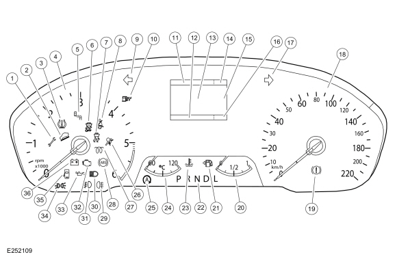
NOTE: The diesel IPC is shown. The gas and North America IPC is similar.
Base IPC

| 1 | Powertrain malfunction (wrench) indicator |
| 2 | Grade assist indicator |
| 3 | TPMS indicator |
| 4 | Tachometer |
| 5 | BLIS off indicator |
| 6 | Stabilty-traction control disabled (sliding car OFF icon) indicator |
| 7 | Stabilty-traction control (sliding car icon) indicator |
| 8 | Seatbelt warning indicator |
| 9 | LH turn indicator |
| 10 | Water-in-fuel indicator (diesel only) |
| 11 | Message center menu display |
| 12 | Trip odometer mileage display area |
| 13 |
|
| 14 | Outside Air Temperature (OAT) display |
| 15 | Sub-menu location identification |
| 16 |
|
| 17 | RH turn indicator |
| 18 | Speedometer |
| 19 | Brake warning indicator |
| 20 | Fuel gauge |
| 21 | Low fuel indicator |
| 22 | PRNDL display |
| 23 | Engine over-temperature warning indicator |
| 24 | Temperature gauge |
| 25 | Auto stop-start indicator (if equipped) |
| 26 | Airbag warning indicator |
| 27 | Wait to start indicator (diesel and E100 only) |
| 28 | ABS indicator |
| 29 | Rear fog lamp indicator (if equipped) |
| 30 | High beam indicator |
| 31 | Front fog lamp indicator |
| 32 | MIL |
| 33 | Low oil pressure warning indicator |
| 34 | Lights on (side marker position) indicator |
| 35 | Door ajar indicator |
| 36 | Charging system warning indicator |
NOTE: The diesel IPC is shown. The gas and North America IPC is similar.
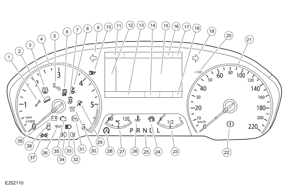
The mid-level and high-level Instrument Panel Clusters (IPCs) appear basically the same except the mid-level IPC uses a monochromatic message center display and the high-level IPC uses a color message center display.
Mid-Level and High-Level IPC

| 1 | Powertrain malfunction (wrench) indicator |
| 2 | Grade assist indicator |
| 3 | TPMS indicator |
| 4 | Tachometer |
| 5 | BLIS off indicator |
| 6 | Stabilty-traction control disabled (sliding car OFF icon) indicator |
| 7 | Stabilty-traction control (sliding car icon) indicator |
| 8 | Seatbelt warning indicator |
| 9 | LH turn indicator |
| 10 | Water-in-fuel indicator (diesel only) |
| 11 | Trip odometer mileage display area |
| 12 | Main message center menu |
| 13 |
|
| 14 | Odometer display |
| 15 | Main message center display area |
| 16 | Frost RTT indicator |
| 17 | Outside Air Temperature (OAT) display |
| 18 | Compass display |
| 19 | RH turn indicator |
| 20 | Overspeed indicator (Gulf Coast Countries [GCC] only) |
| 21 | Speedometer |
| 22 | Brake warning indicator |
| 23 | Fuel gauge |
| 24 | Low fuel indicator |
| 25 | PRNDL display |
| 26 | Engine over-temperature warning indicator |
| 27 | Temperature gauge |
| 28 | Auto stop-start indicator (if equipped) |
| 29 | Airbag warning indicator |
| 30 | Wait to start indicator (diesel and E100 only) |
| 31 | ABS indicator |
| 32 | Rear fog lamp indicator (if equipped) |
| 33 | High beam indicator |
| 34 | Front fog lamp indicator |
| 35 | MIL |
| 36 | Low oil pressure warning indicator |
| 37 | Lights on (side marker position) indicator |
| 38 | Door ajar indicator |
| 39 | Charging system warning indicator |
 Description and Operation - Instrument Panel Cluster (IPC) - System Operation and Component Description
System Operation
System Diagram - Gauges
Item
Description
1
IPC
2
GWM
3
PCM
4
Fuel level sender
5
Tachometer
6
Speedometer
7
Temperature
8
Fuel
9
AWD
Network Message Chart - Gauges
Module Network Input Messages -..
Other information:
Ford Ecosport 2014-2025 Service and Repair Manual: Removal and Installation - Selector Lever Bezel
Special Tool(s) / General Equipment Interior Trim Remover Removal All vehicles Remove the selector lever knob. Refer to: Selector Lever Knob (307-05 Automatic Transmission External Controls, Removal and Installation). Selector lever knobs without a SelectShift® switch Remove the selector lever bezel trim ring. Use the G..
Ford Ecosport 2014-2025 Service and Repair Manual: Removal and Installation - Wiper Linkage Assembly
Removal NOTICE: Make sure that the wiper motor is in the park position. NOTE: Removal steps in this procedure may contain installation details. Remove the cowl panel. Refer to: Cowl Panel (501-02 Front End Body Panels, Removal and Installation). Disconnect the windshield wiper motor electrical connector. ..

