Ford Ecosport: Steering Column / Removal and Installation - Steering Column - LHD
Removal
NOTICE: To prevent damage to the clockspring, make sure the front wheels are in the straight-ahead position.
NOTICE: Precise tolerances are required when manufacturing a steering column. Never install a repaired, rebuilt, aftermarket, or remanufactured steering column. Always install a new steering column. Failure to follow this direction can result in steering column failure.
NOTE: Removal steps in this procedure may contain installation details.
-
NOTE: This step is only necessary when installing a new component.
If installing a new steering column, connect the scan tool and upload the module configuration information from the PSCM .
Refer to: Module Configuration - System Operation and Component Description (418-01 Module Configuration, Description and Operation).
-
NOTE: This step is only necessary when installing a new component.
Remove the steering column lock and ignition switch housing.
Refer to: Steering Column Lock and Ignition Switch Housing (211-05 Steering Wheel and Column Electrical Components, Removal and Installation).
-
NOTE: This step is not necessary when installing a new component.
Remove the steering column shrouds.
Refer to: Steering Column Shrouds (501-05 Interior Trim and Ornamentation, Removal and Installation).
-
NOTICE: Make sure that the steering wheel does not rotate or damage to the clockspring may occur.
NOTE: This step is not necessary when installing a new component.
Secure the steering wheel.
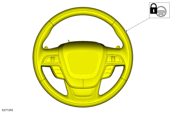 |
-
If equipped.
Remove the driver knee airbag.
Refer to: Driver Knee Airbag (501-20B Supplemental Restraint System, Removal and Installation).
-
NOTE: This step is not necessary when installing a new component.
Disconnect the electrical connectors and detach the wiring harness from the SCCM .
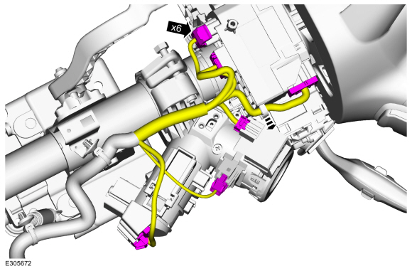 |
-
Detach the wiring harness from the steering column.
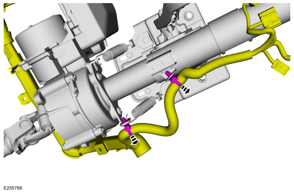 |
-
-
Disconnect the electrical connectors from the EPAS control module.
-
Unclip and position aside the steering column wiring harness.
-
Disconnect the electrical connectors from the EPAS control module.
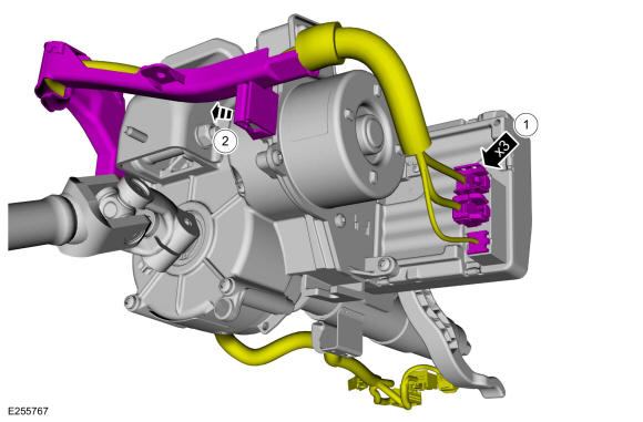 |
-
-
 WARNING:
Do not reuse steering column shaft bolts. This
may result in fastener failure and steering column shaft detachment or
loss of steering control. Failure to follow this instruction may result
in serious injury to vehicle occupant(s).
NOTICE: DO NOT hammer, pry or force steering column and column shafts during installation or removal. Failure to follow this instruction may cause damage to steering components that could lead to loss of steering control during vehicle operation and could result in serious personal injury or death.
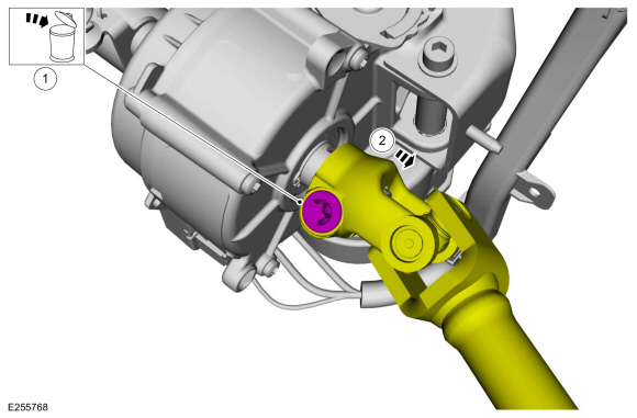
Remove and discard the intermediate steering shaft-to-steering column bolt.
Torque: 25 lb.ft (34 Nm)
-
Separate the intermediate steering shaft from the steering column.
-
 |
-
-
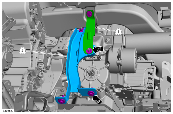
Remove the retainers and the support bracket.
Torque: 71 lb.in (8 Nm)
-
Remove the retainers and the instrument panel airbag mounting bracket.
Torque: 71 lb.in (8 Nm)
-
Remove the retainers and the support bracket.
 |
-
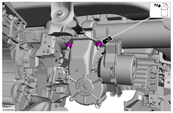
Remove and discard the rear steering column mounting nuts.
Torque: 18 lb.ft (25 Nm)
 |
-
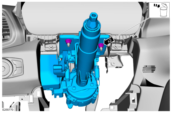
Remove and discard the forward steering column mounting nuts and remove the steering column.
Torque: 18 lb.ft (25 Nm)
 |
Installation
-
To install, reverse the removal procedure.
-
NOTE: This step is only necessary when installing a new component.
If a new steering column was installed, download the PSCM configuration from the scan tool to the new PSCM .
Refer to: Module Configuration - System Operation and Component Description (418-01 Module Configuration, Description and Operation).
-
-
NOTE: Steering wheel and road wheels should be in straight position during the engine ON, after the new ECU / Steering column assembled.
-
NOTE: Do not switch ON engine at steering wheel turned condition prior to steering angle calibration
-
Drive the vehicle above 60km/h (37 mph) for a
minimum of 1 km while maintaining the steering wheel in a straight ahead
position with minimal steering input for at least 30 seconds. When
completed correctly, the back-up camera's active guidelines will be
available. Repeat the process as necessary.
-
 Removal and Installation - Steering Column Shaft
Removal
NOTE:
Removal steps in this procedure may contain installation details.
NOTICE:
Do not allow the steering column to rotate while the
steering column shaft is disconnected or damage to the steering column
internal sensor may result...
Other information:
Ford Ecosport 2014-2025 Service and Repair Manual: Removal and Installation - Rear Brake Flexible Hose
Removal All vehicles NOTE: Removal steps in this procedure may contain installation details. Remove the wheel and tire. Refer to: Wheel and Tire (204-04A Wheels and Tires, Removal and Installation). Vehicles With: FWD Disconnect the brake tube fitting...
Ford Ecosport 2014-2025 Service and Repair Manual: Removal and Installation - Hood Latch Release Cable
Removal Remove the air cleaner. Refer to: Air Cleaner (303-12A Intake Air Distribution and Filtering - 1.0L EcoBoost (92kW/125PS), Removal and Installation). Refer to: Air Cleaner (303-12B Intake Air Distribution and Filtering - 1...

