Ford Ecosport: Side Panel Sheet Metal Repairs / Removal and Installation - Side Panel
Special Tool(s) / General Equipment
| Resistance Spotwelding Equipment | |
| Spherical Cutter | |
| Hot Air Gun | |
| Air Body Saw | |
| 8 mm Drill Bit | |
| MIG/MAG Welding Equipment | |
| Spot Weld Drill Bit | |
| Locking Pliers |
Materials
| Name | Specification |
|---|---|
| Metal Bonding Adhesive TA-1, TA-1-B, 3M™ 08115, LORD Fusor® 108B, Henkel Teroson EP 5055 |
- |
| Seam Sealer TA-2-B, 3M™ 08308, LORD Fusor® 803DTM |
- |
| Flexible Foam Repair 3M™ 08463, LORD Fusor® 121 |
- |
Removal
NOTICE: Sectioning may not take place within 50 mm of any restraints, hinges or door striker mounting points. Failure to meet this guideline may result in compromising structural integrity.
NOTE: The body side may be sectioned providing the above sectioning guideline is adhered. The following procedure assumes full component replacement. Adjust to meet repair needs.
NOTE: It is highly recommended the replacement panel be present before making any sectioning cuts on the vehicle.
NOTE: Left hand (LH) side shown, right hand (RH) side similar.
NOTE: Factory welds may be substituted with resistance or metal inert gas (MIG) plug welds. Resistance welds may not be placed directly over original location. They must be placed adjacent to original location and match factory welds in quantity. Metal inert gas (MIG) plug welds must equal factory welds in both location and quantity.
NOTE: Adequately protect all adjacent areas against cutting, grinding and welding procedures.
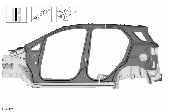
-
Possible sectioning points.
 |
-
Depower the SRS .
Refer to: Supplemental Restraint System (SRS) Depowering (501-20B Supplemental Restraint System, General Procedures).
-
If required:
Dimensionally restore the vehicle to pre-damaged condition.
Refer to: Body and Frame (501-26 Body Repairs - Vehicle Specific Information and Tolerance Checks, Description and Operation).
-
Remove the hood.
Refer to: Hood (501-02 Front End Body Panels, Removal and Installation).
-
Remove the fender and cowl panel grille.
Refer to: Fender (501-02 Front End Body Panels, Removal and Installation).
Refer to: Cowl Panel Grille (501-02 Front End Body Panels, Removal and Installation).
-
Remove the front and rear door.
Refer to: Front Door (501-03 Body Closures, Removal and Installation).
Refer to: Rear Door (501-03 Body Closures, Removal and Installation).
-
Remove the roof panel.
Refer to: Roof Panel (501-28 Roof Sheet Metal Repairs, Removal and Installation).
-
Remove the front door hinges.
 |
-
Remove the front door striker and rear door hinges.
Refer to: B-Pillar Outer Panel (501-29 Side Panel Sheet Metal Repairs, Removal and Installation).
-
Position the carpeting and the wiring harness away from the working area.
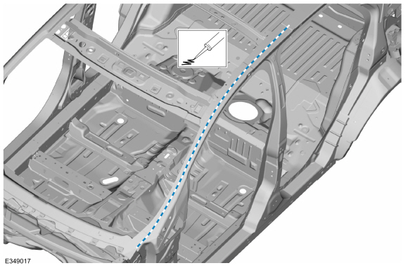
-
Carefully cut the outer panel only.
Use the General Equipment: Air Body Saw
Use the General Equipment: Spherical Cutter
 |
-
Remove the welds.
Use the General Equipment: Spot Weld Drill Bit
 |
-
Remove the welds.
Use the General Equipment: Spot Weld Drill Bit
 |
-
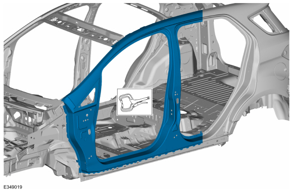
NOTE: Pay particular attention to adhesive, sealer and noise, vibration and harshness (NVH) materials to aid in installation.
Remove the body side section.
Use the General Equipment: Hot Air Gun
 |
Installation
NOTE: Left hand (LH) side shown, right hand (RH) side similar.
NOTE: Factory welds may be substituted with resistance or metal inert gas (MIG) plug welds. Resistance welds may not be placed directly over original location. They must be placed adjacent to original location and match factory welds in quantity. Metal inert gas (MIG) plug welds must equal factory welds in both location and quantity.
NOTE: Adequately protect all adjacent areas against cutting, grinding and welding procedures.
-
Carefully cut the replacement body side to fit the repair area and drill plug weld holes.
Use the General Equipment: Air Body Saw
Use the General Equipment: Spherical Cutter
Use the General Equipment: 8 mm Drill Bit
 |
-
Apply adhesive.
Material: Metal Bonding Adhesive / TA-1, TA-1-B, 3M™ 08115, LORD Fusor® 108B, Henkel Teroson EP 5055
 |
-
Apply adhesive.
Material: Metal Bonding Adhesive / TA-1, TA-1-B, 3M™ 08115, LORD Fusor® 108B, Henkel Teroson EP 5055
 |
-
Install, properly position and clamp the replacement body side.
Use the General Equipment: Locking Pliers
 |
-
Install the welds.
Use the General Equipment: Resistance Spotwelding Equipment
 |
-
Install the welds.
Use the General Equipment: Resistance Spotwelding Equipment
 |
-
Install the welds.
Use the General Equipment: MIG/MAG Welding Equipment
 |
-
Dress all welds as required using typical metal finishing techniques and materials.
-
Apply NVH material in areas noted during removal.
Material: Flexible Foam Repair / 3M™ 08463, LORD Fusor® 121
 |
-
Metal finish all welds as necessary using typical metal finishing techniques.
-
Seam Sealing:
All seams must be sealed to production level.
Material: Seam Sealer / TA-2-B, 3M™ 08308, LORD Fusor® 803DTM
 |
-
Refinish the entire repair using a Ford approved paint system.
-
Restore corrosion protection.
Refer to: Corrosion Prevention (501-25 Body Repairs - General Information, General Procedures).
-
Reposition the carpeting and the wiring harness to original location.
-
Install the roof.
Refer to: Roof Panel (501-28 Roof Sheet Metal Repairs, Removal and Installation).
-
Install the front door hinges.
Torque: 22 lb.ft (30 Nm)
|
-
Install the front door striker and rear door hinges.
Refer to: B-Pillar Outer Panel (501-29 Side Panel Sheet Metal Repairs, Removal and Installation).
-
Install the front fender, splash shield and the cowl panel grille.
Refer to: Fender (501-02 Front End Body Panels, Removal and Installation).
Refer to: Cowl Panel Grille (501-02 Front End Body Panels, Removal and Installation).
-
Install the hood.
Refer to: Hood (501-02 Front End Body Panels, Removal and Installation).
-
Install and align the front and rear doors.
Refer to: Front Door (501-03 Body Closures, Removal and Installation).
Refer to: Front Door Alignment (501-03 Body Closures, General Procedures).
Refer to: Rear Door (501-03 Body Closures, Removal and Installation).
Refer to: Rear Door Alignment (501-03 Body Closures, General Procedures).
-
Repower the SRS .
Refer to: Supplemental Restraint System (SRS) Repowering (501-20B Supplemental Restraint System, General Procedures).


Other information:
Ford Ecosport 2014-2025 Service and Repair Manual: Diagnosis and Testing - Pinpoint Test - DTC: H, Vehicles With: Rear Seat Side Airbag
B0052:11, B0052:12, B0052:13, B0052:1D Refer to Wiring Diagrams Cell 46 for schematic and connector information. Normal Operation and Fault Conditions The RCM continuously monitors the passenger seatbelt buckle sensor circuits for the following faults: Open circuit Short to voltage Short to ground Current out of range Faulted passenger..
Ford Ecosport 2014-2025 Service and Repair Manual: Removal and Installation - Roof Rear Frame
Special Tool(s) / General Equipment Resistance Spotwelding Equipment Spot Weld Drill Bit Locking Pliers Materials Name Specification Seam SealerTA-2-B, 3M™ 08308, LORD Fusor® 803DTM - Removal NOTE: Factory welds may be substituted with resistance or metal inert gas (MIG) plug welds. Resistance welds may not be placed di..
Categories
- Manuals Home
- 2nd Gen Ford Ecosport Service Manual (2014 - 2025)
- General Procedures - Battery Charging
- Automatic Transmission - 6-Speed Automatic Transmission – 6F35
- Climate Control System - General Information
- Engine
- Removal and Installation - Fuel Pump and Sender Unit
Removal and Installation - Oil Pressure Switch
Materials
Name Specification Motorcraft® Thread Sealant with PTFETA-24-B WSK-M2G350-A2
Removal
NOTE: Removal steps in this procedure may contain installation details.
With the vehicle in NEUTRAL, position it on a hoist.Refer to: Jacking and Lifting - Overview (100-02 Jacking and Lifting, Description and Operation).
If equipped, remove the bolts and the underbody shield.