Ford Ecosport: Rear End Sheet Metal Repairs / Removal and Installation - Rear Floor Panel
Special Tool(s) / General Equipment
| Scraper for Straight Edges | |
| Spherical Cutter | |
| Hot Air Gun | |
| 8 mm Drill Bit | |
| MIG/MAG Welding Equipment | |
| Spot Weld Drill Bit | |
| Locking Pliers |
Materials
| Name | Specification |
|---|---|
| Seam Sealer TA-2-B, 3M™ 08308, LORD Fusor® 803DTM |
- |
Removal
NOTE: To minimize the intrusiveness of the repair, the floor panel may be sectioned if desired. See floor panel sectioning in this section. The following assumes full component replacement. Adjust to meet repair needs.
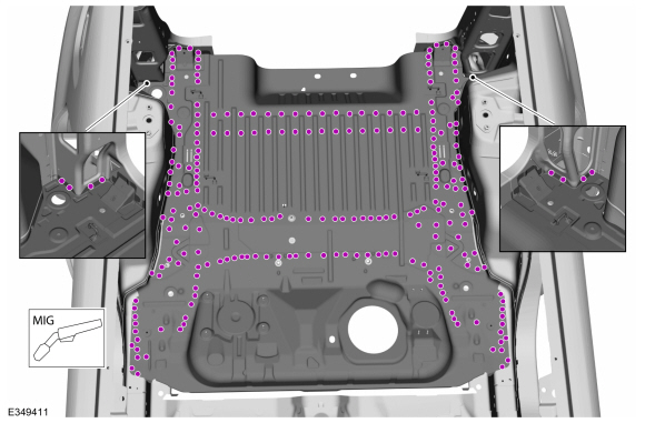
NOTE: Rear doors, trunk panel, roof and parcel shelf removed for clarity.
NOTE: Factory welds may be substituted with resistance or metal inert gas (MIG) plug welds. Resistance welds may not be placed directly over original location. They must be placed adjacent to original location and match factory welds in quantity. Metal inert gas (MIG) plug welds must equal factory welds in both location and quantity.
NOTE: Adequately protect all adjacent areas against cutting, grinding and welding procedures.
-
Depower the SRS .
Refer to: Supplemental Restraint System (SRS) Depowering (501-20B Supplemental Restraint System, General Procedures).
-
If Required:
Dimensionally restore the vehicle to pre-damage condition.
Refer to: Body and Frame (501-26 Body Repairs - Vehicle Specific Information and Tolerance Checks, Description and Operation).
-
Remove the rear seat.
Refer to: Rear Seat Backrest (501-10B Rear Seats, Removal and Installation).
-
Remove the B, C and D-pillar trim panels.
Refer to: B-Pillar Trim Panel (501-05 Interior Trim and Ornamentation, Removal and Installation).
Refer to: C-Pillar Lower Trim Panel (501-05 Interior Trim and Ornamentation, Removal and Installation).
Refer to: D-Pillar Trim Panel (501-05 Interior Trim and Ornamentation, Removal and Installation).
-
Remove the Loadspace Trim Panel.
Refer to: Loadspace Trim Panel (501-05 Interior Trim and Ornamentation, Removal and Installation).
-
Position the carpeting and the wiring harness away from the working area.
-
Remove the Back Panel and Reinforcement.
Refer to: Back Panel and Reinforcement (501-30 Rear End Sheet Metal Repairs, Removal and Installation).
-
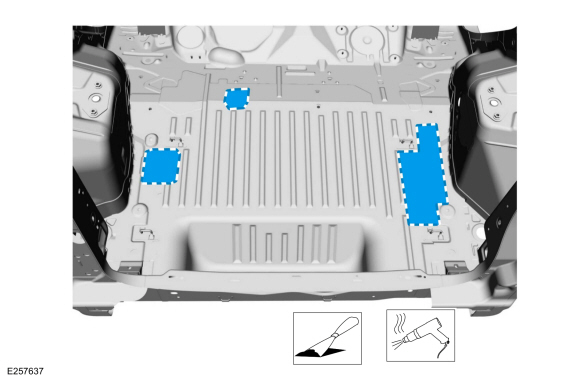
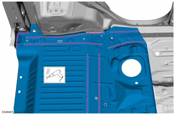
NOTE: Use of a heat gun may aid in removing the mastic material.
Remove the NVH mastic pads.
Use the General Equipment: Hot Air Gun
Use the General Equipment: Scraper for Straight Edges
 |
-
NOTE: Left hand (LH) side shown, right hand (RH) side similar.
Remove the seam sealer.
Use the General Equipment: Hot Air Gun
Use the General Equipment: Scraper for Straight Edges
 |
-
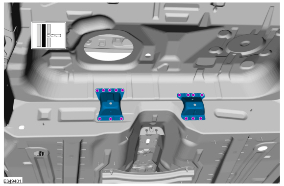
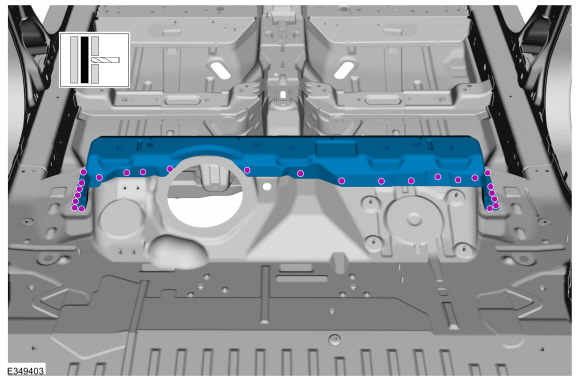
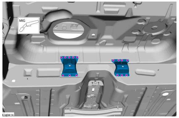
Remove the welds and fuel tank bracket.
Use the General Equipment: Spot Weld Drill Bit
 |
-
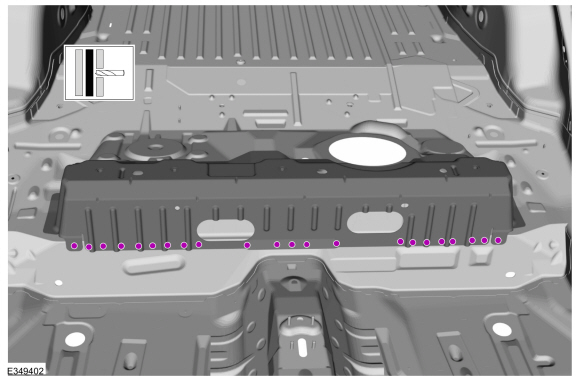
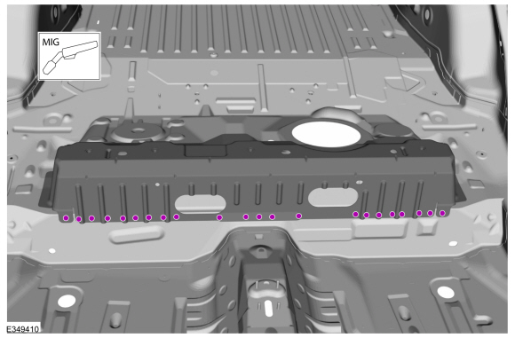
Remove the welds.
Use the General Equipment: Spot Weld Drill Bit
 |
-
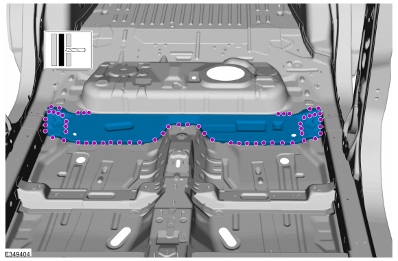
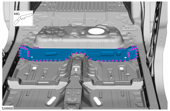
Remove the welds and reinforcement.
Use the General Equipment: Spot Weld Drill Bit
 |
-
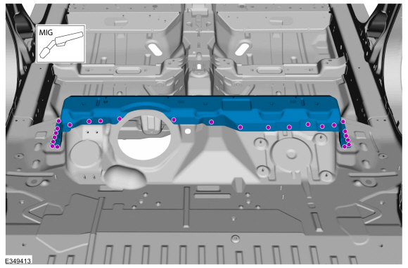
Remove the welds and center floor panel.
Use the General Equipment: Spot Weld Drill Bit
 |
-
Remove the welds.
Use the General Equipment: Spot Weld Drill Bit
 |
-
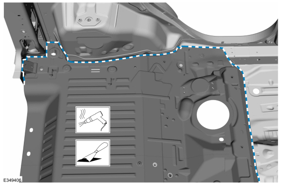
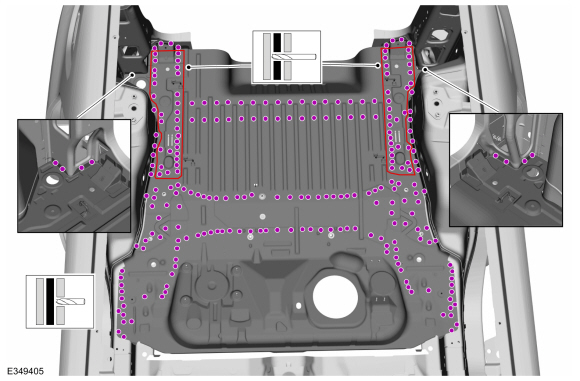
NOTE: Left hand (LH) side shown, right hand (RH) side similar.
Remove the welds.
Use the General Equipment: Spot Weld Drill Bit
Use the General Equipment: Spherical Cutter
 |
-
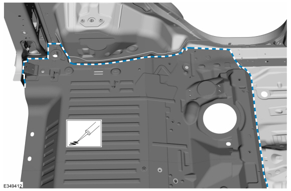
NOTE: Pay particular attention to the location of noise, vibration and harshness (NVH) materials, adhesive and sealer to aid in installation.
NOTE: The use of heat may be required to soften adhesives and sealers.
NOTE: Left hand (LH) side shown, right hand (RH) side similar.
On all side:
Remove the rear floor panel.
Use the General Equipment: Hot Air Gun
 |
Installation
NOTE: Rear doors, trunk panel, roof and parcel shelf removed for clarity.
NOTE: Factory welds may be substituted with resistance or metal inert gas (MIG) plug welds. Resistance welds may not be placed directly over original location. They must be placed adjacent to original location and match factory welds in quantity. Metal inert gas (MIG) plug welds must equal factory welds in both location and quantity.
NOTE: Adequately protect all adjacent areas against cutting, grinding and welding procedures.
-
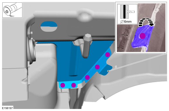
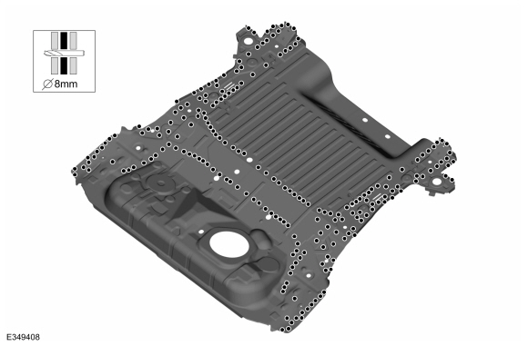
Drill plug weld holes in the replacement rear floor panel.
Use the General Equipment: 8 mm Drill Bit
 |
-
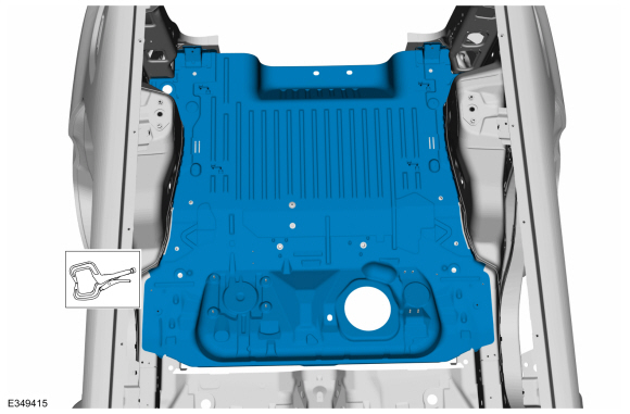
Install, properly position and clamp the rear floor panel.
Use the General Equipment: Locking Pliers
 |
-
NOTE: Left hand (LH) side shown, right hand (RH) side similar.
Install the welds.
Use the General Equipment: Spot Weld Drill Bit
Use the General Equipment: Spherical Cutter
 |
-
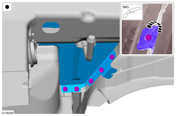
Install the welds.
Use the General Equipment: MIG/MAG Welding Equipment
 |
-
Install the welds and center floor panel.
Use the General Equipment: MIG/MAG Welding Equipment
 |
-
Install the welds and reinforcement.
Use the General Equipment: MIG/MAG Welding Equipment
 |
-
Install the welds.
Use the General Equipment: MIG/MAG Welding Equipment
 |
-
install the welds and fuel tank bracket.
Use the General Equipment: MIG/MAG Welding Equipment
 |
-
Dress all welds as required using typical metal finishing techniques.
-
NOTE: Left hand (LH) side shown, right hand (RH) side similar.
Seam Sealing Entire Perimeter:
All seams must be sealed to production level.
Material: Seam Sealer / TA-2-B, 3M™ 08308, LORD Fusor® 803DTM
 |
-
Refinish the entire repair using a Ford approved paint system.
-
Restore corrosion protection.
Refer to: Corrosion Prevention (501-25 Body Repairs - General Information, General Procedures).
-
Rear floor panel all seams must be sealed to production level.
-
install the Back Panel and Reinforcement.
Refer to: Back Panel and Reinforcement (501-30 Rear End Sheet Metal Repairs, Removal and Installation).
-
Apply locally obtained butyl noise, vibration and
harshness (NVH) material in all areas noted on original panel during
removal.
-
Transfer or install new floor panel plugs.
-
Reposition the carpeting and the wiring harness to original location.
-
Install the luggage compartment trim.
-
Install the rear seat.
Refer to: Rear Seat Backrest (501-10B Rear Seats, Removal and Installation).
-
Remove the Loadspace Trim Panel.
Refer to: Loadspace Trim Panel (501-05 Interior Trim and Ornamentation, Removal and Installation).
-
Install the B, C and D-pillar trim panels.
Refer to: B-Pillar Trim Panel (501-05 Interior Trim and Ornamentation, Removal and Installation).
Refer to: C-Pillar Lower Trim Panel (501-05 Interior Trim and Ornamentation, Removal and Installation).
Refer to: D-Pillar Trim Panel (501-05 Interior Trim and Ornamentation, Removal and Installation).
-
Repower the SRS .
Refer to: Supplemental Restraint System (SRS) Repowering (501-20B Supplemental Restraint System, General Procedures).
 Removal and Installation - Rear Exhaust Mounting Bracket
Special Tool(s) /
General Equipment
8 mm Drill Bit
MIG/MAG Welding Equipment
Spot Weld Drill Bit
Locking Pliers
Removal
NOTE:
Factory welds may be substituted with resistance or metal
inert gas (MIG) plug welds...
 Removal and Installation - Rear Floor Panel Crossmember
Special Tool(s) /
General Equipment
8 mm Drill Bit
MIG/MAG Welding Equipment
Spot Weld Drill Bit
Locking Pliers
Materials
Name
Specification
Seam SealerTA-2-B, 3M™ 08308, LORD Fusor® 803DTM
-
Removal
NOTE:
Factory welds may be substituted with resistance or metal
inert gas (MIG) plug welds...
Other information:
Ford Ecosport 2014-2026 Service and Repair Manual: Description and Operation - Final Drive
Final Drive Component Exploded View Item Description 1 Drive chain drive sprocket 2 Drive chain 3 Drive chain driven sprocket 4 Final drive planetary sun gear 5 Differential assembly 6 Final drive planet..
Ford Ecosport 2014-2026 Service and Repair Manual: Removal and Installation - Rear Shock Absorber
Special Tool(s) / General Equipment Transmission Jack Vehicle/Axle Stands Removal NOTICE: Suspension fasteners are critical parts that affect the performance of vital components and systems. Failure of these fasteners may result in major service expense. Use the same or equivalent parts if replacement is necessary. Do not use a replacement part of lesser ..
Categories
- Manuals Home
- 2nd Gen Ford Ecosport Service Manual (2014 - 2026)
- Removal and Installation - Starter Motor
- Service Information
- Removal and Installation - Evaporative Emission Canister Purge Valve
- Removal and Installation - Roof Rail
- Removal and Installation - Blower Motor
Removal and Installation - Steering Column Shaft
Removal
NOTE: Removal steps in this procedure may contain installation details.
NOTICE: Do not allow the steering column to rotate while the steering column shaft is disconnected or damage to the steering column internal sensor may result.
NOTE: Use a steering wheel holding device (such as Hunter® 28-75-1 or equivalent)
Hold the steering wheel in the straight-ahead position.