Ford Ecosport: Front Drive Halfshafts / Removal and Installation - Outer Constant Velocity (CV) Joint Boot
Special Tool(s) / General Equipment
 |
204-169 Clamping Tool, Boot Retaining Clamp |
 |
205-310 Remover, Bearing/Gear |
 |
308-110 Remover/Installer, Front Housing |
| Vise | |
Removal
NOTE: Removal steps in this procedure may contain installation details.
-
Remove the inner CV joint boot.
Refer to: Inner Constant Velocity (CV) Joint Boot (205-04 Front Drive Halfshafts, Removal and Installation).
-
If equipped.
Mark the damper position on the halfshaft.
 |
-
If equipped.
Using the special tool, remove the damper.
Use Suggested Tool: 205-310 Remover, Bearing/Gear. Tool shown or a commercially available equivalent can be used.
Use the General Equipment: Vise
 |
-
Remove and discard the CV joint boot clamps.
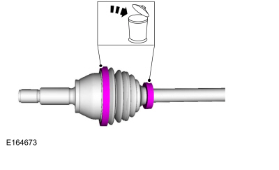 |
-
Remove the outer CV joint boot.
 |
Installation
-
NOTE: Make sure that the component is clean, free of foreign material and lubricant.
Clean the CV joint housing.
 |
-
Apply the grease sachet supplied with the boot service kit evenly in the CV joint housing.
 |
-
Apply the grease sachet supplied with the boot service kit evenly in the CV joint boot.
 |
-
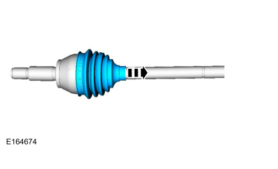
Release any trapped air.
 |
-
NOTE: Make sure that new components are installed.
NOTE: Do not move the CV joint housing. Make sure that the CV joint boot is installed with the boot in the CV groove.
-
Using the special tool, position back the CV boot and install the new large halfshaft boot clamp.
Use Special Service Tool: 204-169 Clamping Tool, Boot Retaining Clamp.
-
Using the special tool, position back the CV boot and install the new large halfshaft boot clamp.
 |
-
NOTE: Make sure that the component aligns with the installation mark.
If equipped.
Using the special tool, install the damper.
Use Suggested Tool: 308-110 Remover/Installer, Front Housing. Tool shown or a commercially available equivalent can be used.
 |
-
Install the inner CV joint boot.
Refer to: Inner Constant Velocity (CV) Joint Boot (205-04 Front Drive Halfshafts, Removal and Installation).
 Removal and Installation - Inner Constant Velocity (CV) Joint Boot
Special Tool(s) /
General Equipment
308-046Installer, Transmission Extension Housing Bushing/Seal
Flat Headed Screw Driver
Boot Clamp Pliers
Puller
Wooden Block
Copper Hammer
Bearing Separator
Vise
Vise Jaw Protectors
Removal
NOTE:
Removal steps in this procedure may contain installation details...
 Removal and Installation - Front Halfshaft RH - 2.0L Duratec-HE (125kW/170PS) – MI4, FWD
Special Tool(s) /
General Equipment
204-161
(T97P-1175-A)
Installer, HalfshaftTKIT-1997-LM2TKIT-1997-F/FM2TKIT-1997-FLM2
205-775Protector, Halfshaft Seal
205-D070
(D93P-1175-B)
Remover, Front Wheel Hub
211-001
(TOOL-3290-D)
Remover, Tie-Rod End
Removal
NOTE:
Removal steps in this procedure may contain installation details...
Other information:
Ford Ecosport 2014-2024 Service and Repair Manual: Diagnosis and Testing - Pinpoint Test - DTC: V
U0140:00 Normal Operation and Fault Conditions The RCM uses information contained in messages from the BCM sent on the HS-CAN . DTC Fault Trigger Conditions DTC Description Fault Trigger Conditions U0140:00 Lost Communication with Body Control Module: No Sub Typ..
Ford Ecosport 2014-2024 Service and Repair Manual: Description and Operation - Tire Pressure Monitoring System (TPMS) - Overview
Overview The BCM monitors the tire pressure in the 4 road tires with tire pressure sensors that communicate the tire pressure via radio signals to the BCM . The tire pressure sensors are battery operated and mounted to the valve stems. All of the controlling software for the TPMS is contained in the BCM . The IPC illuminates the TPMS warning indicator and the message center displa..
Categories
- Manuals Home
- 2nd Gen Ford Ecosport Service Manual (2014 - 2024)
- Body and Paint
- Description and Operation - Evaporative Emissions - System Operation and Component Description
- Removal and Installation - Fuel Pump and Sender Unit
- Engine
- Removal and Installation - Roof Rail
Removal and Installation - Steering Column Shaft
Removal
NOTE: Removal steps in this procedure may contain installation details.
NOTICE: Do not allow the steering column to rotate while the steering column shaft is disconnected or damage to the steering column internal sensor may result.
NOTE: Use a steering wheel holding device (such as Hunter® 28-75-1 or equivalent)
Hold the steering wheel in the straight-ahead position.