Ford Ecosport: Front Seats / Removal and Installation - Front Seat Cushion Cover
Special Tool(s) /
General Equipment
Removal
NOTE:
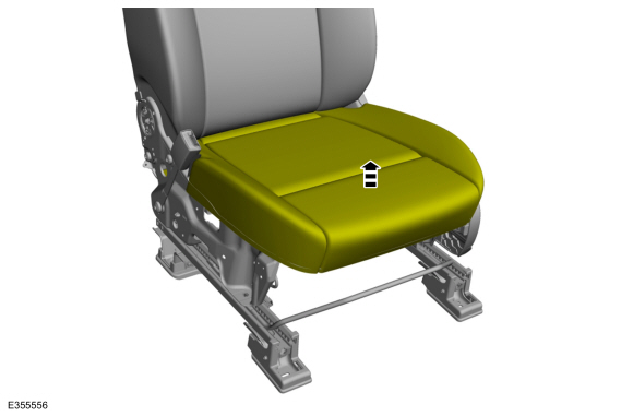
Driver seat shown, except where called out.
NOTE:
Follow the unique instructions or graphics for this step when installing a front passenger seat equipped with OCS.
-
Remove the front seat.
Refer to: Front Seat (501-10A Front Seats, Removal and Installation).
-
If equipped with manual lumbar.
Adjust the manual lumbar to the fully relaxed position.
-
-
If equipped with recline handle.
Remove the clip and the recline handle.
-
If equipped with height adjuster.
Release the retaining tab and remove the height adjuster handle.
-
If equipped with manual lumbar.
Release the retainer and remove the manual lumbar handle.
-
If equipped with manual seat.
-
Remove the screw.
-
Lift the rear of the side shield up and out.
-
Slide forward and remove the side shield.
-
If equipped with power seat.
-
Remove the screw.
-
Lift the rear of the side shield up and out.
-
Slide forward and position the side shield aside.
-
If equipped with power seat.
Position the front seat control switch support bracket aside.
-
Detach the front seat control switch wiring harness.
-
Remove the screws.
-
If equipped with power seat.
Disconnect the electrical connectors and remove the side shield.
-
If equipped with manual lumbar.
Remove the lumbar adjuster.
-
Remove the screws.
-
Detach the lumbar adjuster cable retainer.
-
Detach the lumbar adjuster cable.
-
Remove the screws and the recliner cover.
-
Detach the strap and position the front seat cushion cover apron upward.
-
-
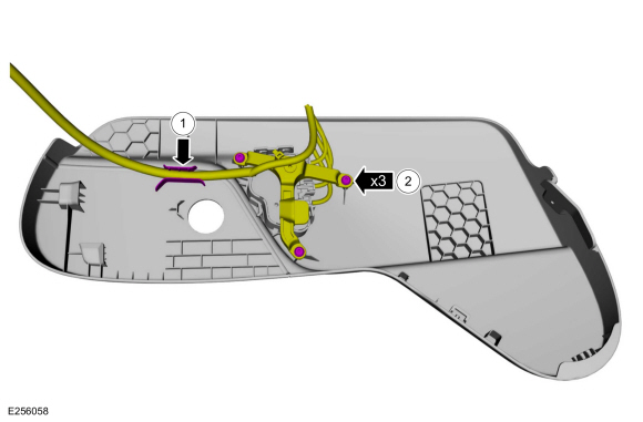
If equipped with heated seat.
Detach the electrical connector retainers.
-
If equipped with heated seat.
Disconnect the front seat cushion heater mat electrical connector.
-
-
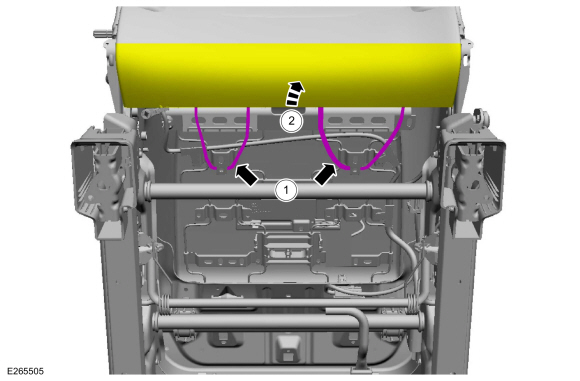
Detach the front seat backrest cover straps.
-
Position the front seat backrest cover up.
-
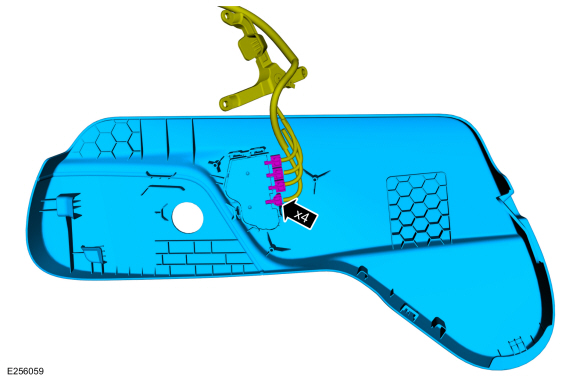
Detach the front seat cushion cover rear J-clips.
-
Route the lumbar cable through the front seat cushion cover.
-
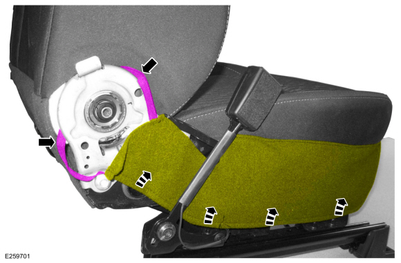
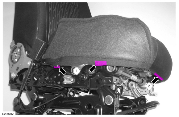
-
On both sides.
Detach the front seat cushion cover J-clips.
-
Detach the front seat cushion cover J-clip.
Driver seat - Type 1
-
Remove the front seat cushion cover and foam as an assembly.
Driver seat - Type 2
-
Remove the front seat cushion cover and foam as an assembly.
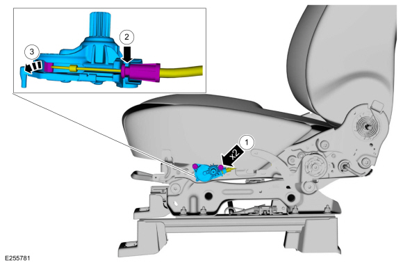
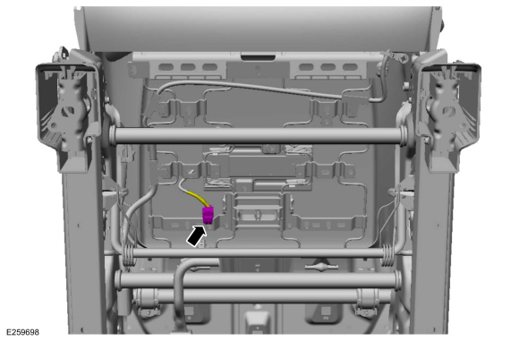
Passenger seat with seatbelt minder
-
Disconnect the seatbelt minder sensor electrical connector.
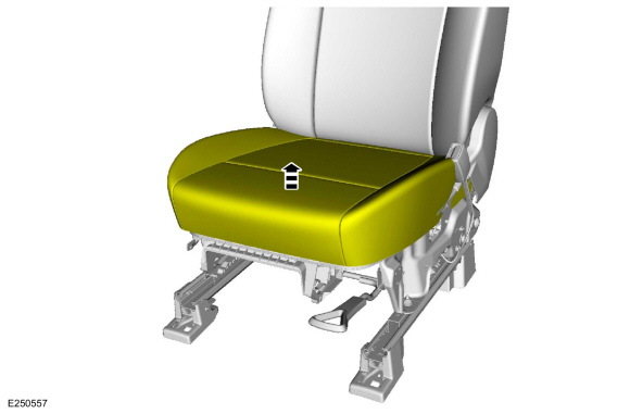
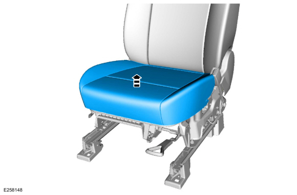
Type 1
-
Lift up on the front seat cushion cover and foam assembly.
Type 2
-
Lift up on the front seat cushion cover and foam assembly.
-
NOTE:
For correct installation, note the location of
the seatbelt minder sensor wiring pigtail as it passes through the seat
track.
Route out the seatbelt minder sensor wiring pigtail
and remove the front seat cushion cover and foam as an assembly.
Passenger seat with OCS
-
Disconnect the OCS sensor.
-
NOTE:
When equipped with an OCS service kit, the OCS is adhered to the bottom
of the front seat cushion foam. This requires the cushion cover, foam
and OCS to be positioned aside as an assembly.
Lift the front seat cushion foam. If the front seat cushion foam and
OCS are adhered together, then the OCS is a service kit. If nothing is
adhered together, then the OCS is OE (original equipment).
-
If equipped with an OE OCS .
Remove the front seat cushion cover and foam as an assembly.
-
NOTE:
Typical OE OCS shown, service kit similar.
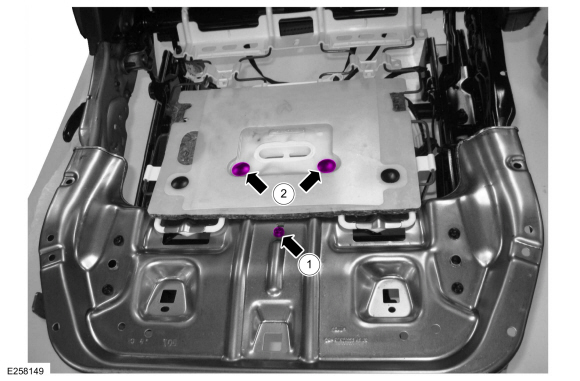
-
Remove the OCS sensor bracket screw.
Torque:
44 lb.in (5 Nm)
-
Remove the OCS pin-type retainers.
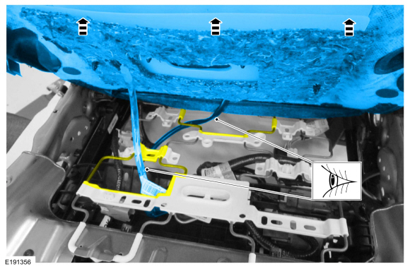
-
NOTE:
For correct installation, note the location of the OCS hose and heater
mat pigtail (if equipped) as it passes through the seat springs.
Route out the OCS
hose, sensor, sensor bracket and front heated seat cushion mat wiring
pigtail (if equipped) from between the front seat cushion support wires
and remove the OCS .
All seats
-
Position the rear portion of the front seat cushion cover from the foam.
-
NOTE:
This step is only necessary when installing a new component.
NOTE:
Follow the unique instructions or graphics for this step in installation.
Remove the hog rings and the front seat cushion cover.
Installation
All seats
-
To install, reverse the removal procedure.
-
Use the General Equipment: Hog Ring Plier
Passenger seat with OCS
-
Install the front passenger seat. Do not prove out the SRS at this time.
Refer to: Front Seat (501-10A Front Seats, Removal and Installation).
-
 WARNING:
Occupant Classification System (OCS) parts are
calibrated as an assembly and must only be replaced in the configuration
they are sold. Never separate parts of an assembly. Failure to follow
this instruction may result in incorrect operation of the OCS and
increases the risk of serious personal injury or death in a crash.
WARNING:
Make sure the front passenger seat repair is
complete, the seat and all attached components (head restraint, seat
side shield, etc.) are correctly assembled, and the seat is correctly
installed to the vehicle before using System Reset to rezero the seat
weight. Failure to follow these instructions may result in incorrect
operation of the occupant classification system (OCS) and increases the
risk of serious personal injury or death in a crash.
NOTICE:
To prevent system failure, take the following precautions before carrying out the OCS reset.
-
Make sure the voltage to the OCSM is greater than 8 volts and less than 18 volts.
-
Make sure the OCS is not below 6º C (42.8º F) or above 36º C (96.7º F) when initiating the OCS
reset process. If the vehicle has been exposed to extreme cold or hot
temperatures, the vehicle must be exposed and kept at a temperature
between 6º C (42.8º F) to 36º C (96.7º F) for a minimum of 30 minutes.
-
Make sure nothing is present on the passenger seat before and during the OCS reset process.
-
Prior to carrying out the OCS reset, make sure a minimum of 8 seconds has elapsed after cycling the ignition switch on.
Using a diagnostic scan tool, carry out the OCS reset. Cycle the ignition switch after the OCS reset.
-
If the first system reset attempt was successful, proceed to prove out the SRS .
-
If the first system reset attempt was not successful, carry out a thorough visual inspection of the OCS
connector and wiring for damage, pressure sensor hose for kinks and or
damage, and seat-related wiring harness and body wiring harness
terminals and connectors for damage. Repair any concerns found and
proceed to the next step.
-
Carry out a second OCS reset. Cycle the ignition switch after the OCS
reset. If the second attempt is unsuccessful, install a new OCS service
kit.
-
Prove out the SRS
. Verify all airbags are installed and connected and the ignition is
OFF. Wait 10 seconds then turn the ignition ON and monitor the airbag
warning indicator. The airbag warning indicator illuminates continuously
for approximately 6 seconds and turns off. Continue to monitor the
airbag warning indicator for approximately 30 seconds, as this is the
time required for the RCM to complete testing of the SRS .
-
If a SRS
fault is present, the airbag warning indicator either fails to light,
remains lit continuously or flashes. The flashing may not occur until
approximately 30 seconds after the ignition has been turned from OFF to
ON. If this occurs, diagnose and repair any SRS faults before proceeding with other repairs.
-
If, after the ignition has been turned on for 30
seconds, the airbag warning indicator remains unlit with no chime or
SRS message displayed in the message center, no SRS fault is present.
-
If the airbag warning indicator is inoperative and a SRS
fault exists, a chime sounds in a pattern of 5 sets of 5 beeps or a
message displays in the message center. If this occurs, diagnose and
repair the airbag warning indicator and any SRS faults before proceeding with other repairs.
-
Using a scan tool, clear all Continuous Memory Diagnostic Trouble Codes (CMDTCs) from all modules.
Removal
NOTE:
LHD driver seat shown, RHD driver seat similar.
Remove the front seat.
Refer to: Front Seat (501-10A Front Seats, Removal and Installation)...
Removal
Lumbar adjuster
Remove the front seat.
Refer to: Front Seat (501-10A Front Seats, Removal and Installation).
Adjust the manual lumbar to the fully relaxed position...
Other information:
General Equipment
Ford diagnostic equipment
DTC Charts:
Diagnostics
in this manual assume a certain skill level and knowledge of
Ford-specific diagnostic practices. For information about these
practices, REFER to: Diagnostic Methods (100-00 General Information, Description and Operation)...
Transmission Fluid Auxiliary Pump Components
Item
Description
1
Transmission assembly
2
Transmission fluid auxiliary pump supply tube assembly
3
Check ball (part of the transmission fluid auxiliary pump supply tube)
4
Transmission fluid auxiliary..


 Removal and Installation - Front Seat Control Switch
 Removal and Installation - Front Seat Lumbar Assembly
 WARNING:
Wear eye and ear protection when servicing a vehicle.
Failure to follow this instruction may result in serious personal
injury.
WARNING:
Wear eye and ear protection when servicing a vehicle.
Failure to follow this instruction may result in serious personal
injury.