Ford Ecosport: Bumpers / Removal and Installation - Front Bumper
Special Tool(s) / General Equipment
| Knife |
Removal
NOTE: Removal steps in this procedure may contain installation details.
-
Remove the front bumper cover.
Refer to: Front Bumper Cover (501-19 Bumpers, Removal and Installation).
-
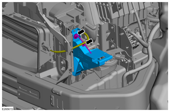
NOTE: LH side only.
-
Detach the retainer and position the wiring harness aside.
-
Remove the bolt and the headlamp stand.
Torque: 44 lb.in (5 Nm)
-
Detach the retainer and position the wiring harness aside.
 |
-
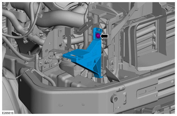
NOTE: RH side only.
Remove the bolt and the headlamp stand.
Torque: 44 lb.in (5 Nm)
 |
-
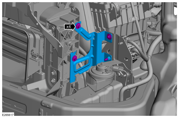
On both sides.
Remove the bolts and the bracket.
Torque: 44 lb.in (5 Nm)
 |
-
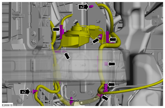
NOTE: LH side only.
-
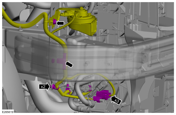
Detach the wiring harness routing retainers.
-
Remove the nut and position the horn and wiring harness assembly aside.
-
Detach the wiring harness routing retainers.
 |
-
NOTE: RH side only.
-
Detach the wiring harness routing retainers.
-
Disconnect the electrical connectors.
-
Remove the nut and position the horn and wiring harness assembly aside.
-
Detach the wiring harness routing retainers.
 |
-
If applicable.
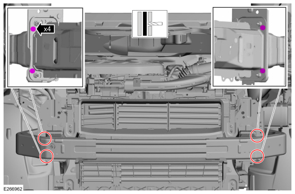
Drill out the spot welds from the front bumper beam.
 |
-
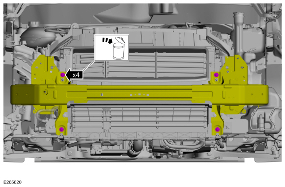
Support the cooling module.
-
Remove and discard the bumper mounting bolts.
 |
-
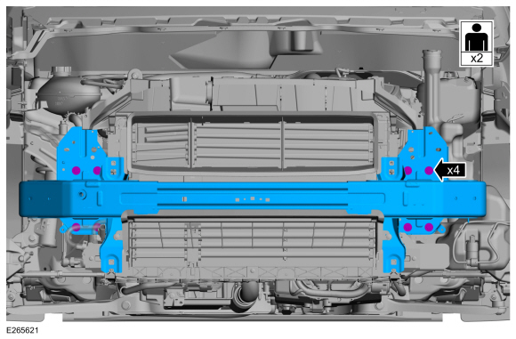
With the help of an assistant.
Remove the bumper mounting bolts and the front bumper.
 |
Installation
-
Measure the depth on the damaged bumper beam bracket.
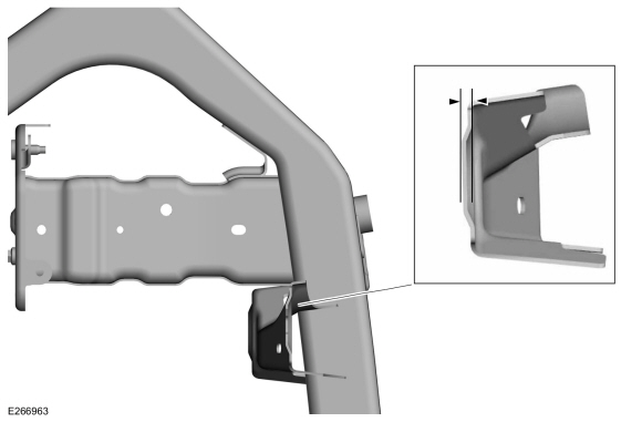 |
-
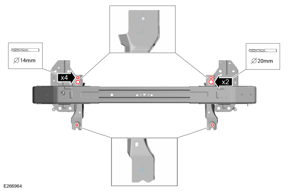
NOTE: The front bumper service component is supplied without the front bumper beam radiator mounting holes present. It is intended that the required holes be drilled in the bracket while performing the service procedure. The location of the holes is marked on the bracket with cross marks.
Drill the front bumper beam radiator mounting holes on the bracket.
 |
-
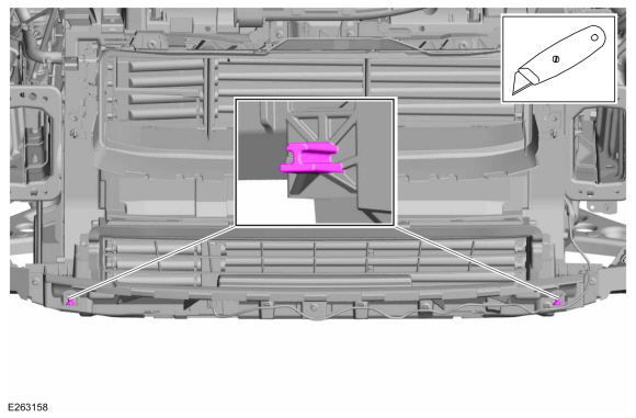
Carefully cut the dowels on the radiator assembly.
Use the General Equipment: Knife
 |
-
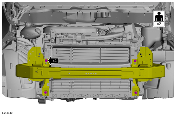
NOTE: Make sure that new bolts are installed.
NOTE: Only tighten the bolts finger tight at this stage.
NOTE: Adjust the shim thickness to achieve correct bumper alignment.
With the help of an assistant.
Install the shim thickness equivalent to the measurement made in step 1, determining the shim thickness will aid the technician to complete the service procedure and achieve the correct bumper alignment.
 |
-
NOTE: Only tighten the bolts finger tight at this stage.
Install the bolts.
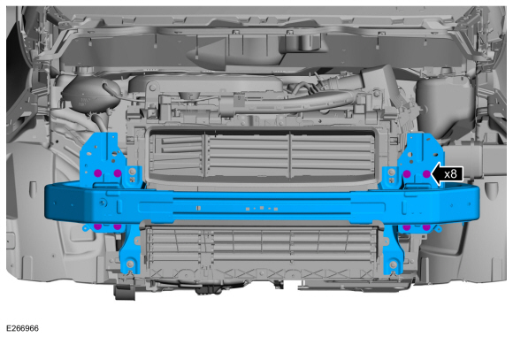 |
-
Tighten the bolts.
Torque:
1 : 80 lb.in (9 Nm)
2 : 18 lb.ft (25 Nm)
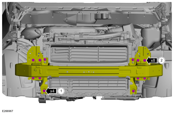 |
-
To install, reverse the removal procedure.
-
Check the body-to-front bumper cover dimensions.
 Bumpers
..
 Removal and Installation - Front Bumper Cover
Removal
NOTE:
Removal steps in this procedure may contain installation details.
Remove the fender splash shield.
Refer to: Fender Splash Shield (501-02 Front End Body Panels, Removal and Installation)...
Other information:
Ford Ecosport 2014-2025 Service and Repair Manual: Removal and Installation - Headlamp Switch
Special Tool(s) / General Equipment Interior Trim Remover Removal NOTE: Removal steps in this procedure may contain installation details. Remove the LH vent. Use the General Equipment: Interior Trim Remover Remove the headlamp switch assembly...
Ford Ecosport 2014-2025 Service and Repair Manual: General Procedures - Liftgate Alignment
Inspection Check liftgate-to-body dimensions. Refer to: Body and Frame (501-26 Body Repairs - Vehicle Specific Information and Tolerance Checks, Description and Operation). Adjustment All alignments Open the liftgate...

 205-153
(T80T-4000-W)
 205-990