Ford Ecosport: Electronic Engine Controls - 2.0L Duratec-HE (129kW/175PS) / Removal and Installation - Crankshaft Position (CKP) Sensor
Special Tool(s) / General Equipment
 |
303-1521 Alignment Tool, Crankshaft Position Sensor TKIT-2010C-FLM |
 |
303-507 Timing Peg, Crankshaft TDC TKIT-2001N-FLM TKIT-2001N-ROW |
| Ford Diagnostic Equipment | |
Removal
NOTE: Do not loosen or remove the crankshaft pulley bolt without first installing the special tools as instructed in this procedure. The crankshaft pulley and the crankshaft timing sprocket are not keyed to the crankshaft. The crankshaft, the crankshaft sprocket and the pulley are fitted together by friction, using diamond washers between the flange faces on each part. For that reason, the crankshaft sprocket is also unfastened if the pulley bolt is loosened. Before any repair requiring loosening or removal of the crankshaft pulley bolt, the crankshaft and camshafts must be locked in place by the special service tools, otherwise severe engine damage can occur.
NOTE: During engine repair procedures, cleanliness is extremely important. Any foreign material, including any material created while cleaning gasket surfaces, that enters the oil passages, coolant passages or the oil pan can cause engine failure.
-
With the vehicle in NEUTRAL, position it on a hoist.
Refer to: Jacking and Lifting - Overview (100-02 Jacking and Lifting, Description and Operation).
-
If equipped, remove the bolts and the underbody shield.
 |
-
Remove the retainers and the accessory drive belt cover.
 |
-
-
Disconnect the CKP sensor electrical connector.
-
Remove the 2 CKP sensor bolts and the CKP sensor.
-
Disconnect the CKP sensor electrical connector.
 |
Installation
-
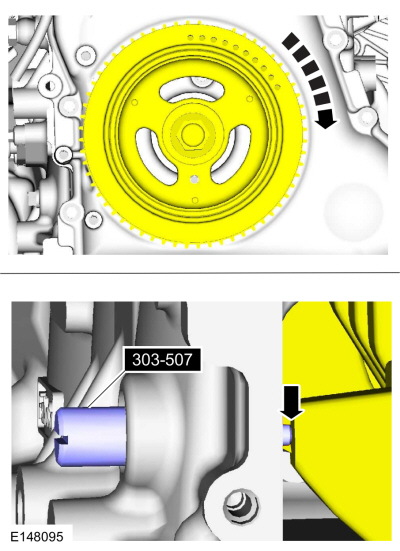
Turn the crankshaft clockwise until the No. 1 piston is 45 degrees BTDC
using the guide holes on the engine front cover and the crankshaft
pulley.
 |
-
Remove the engine plug bolt.
 |
-
Install the Crankshaft TDC Timing Peg.
Use Special Service Tool: 303-507 Timing Peg, Crankshaft TDC.
 |
-
NOTE: The Crankshaft TDC Timing Peg will contact the crankshaft and prevent it from turning past TDC . However, the crankshaft can still be rotated in the counterclockwise direction. The crankshaft must remain at the TDC during CKP sensor installation.
NOTE: The engine front cover is removed from graphic for clarity.
Slowly rotate the crankshaft clockwise until the crankshaft contacts the Crankshaft TDC Timing Peg.
-
The TDC marked tooth on the crankshaft pulley will align with the center line of the CKP sensor.
Use Special Service Tool: 303-507 Timing Peg, Crankshaft TDC.
-
The TDC marked tooth on the crankshaft pulley will align with the center line of the CKP sensor.
 |
-
NOTE: Do not tighten the CKP sensor bolts at this time.
Install the CKP sensor and the 2 CKP sensor bolts.
 |
-
Install the Crankshaft Sensor Alignment Tool.
-
If the Crankshaft Sensor Alignment Tool does not align with the TDC
marked tooth on the crankshaft pulley, loosen the 2 CKP sensor bolts and
adjust the sensor until the tool is installed.
Install Special Service Tool: 303-1521 Alignment Tool, Crankshaft Position Sensor.
-
Tighten the CKP sensor bolts.
Torque: 89 lb.in (10 Nm)
-
If the Crankshaft Sensor Alignment Tool does not align with the TDC
marked tooth on the crankshaft pulley, loosen the 2 CKP sensor bolts and
adjust the sensor until the tool is installed.
-
Remove the Crankshaft Sensor Alignment Tool.
Remove Special Service Tool: 303-1521 Alignment Tool, Crankshaft Position Sensor.
 |
-
Remove the Crankshaft TDC Timing Peg.
Remove Special Service Tool: 303-507 Timing Peg, Crankshaft TDC.
|
-
Install the engine plug bolt.
Torque: 177 lb.in (20 Nm)
|
-
Connect the CKP sensor electrical connector.
 |
-
Install the accessory drive belt cover and retainers.
Torque: 18 lb.ft (25 Nm)
|
-
Install the underbody shield and the retainers.
|
-
After completing the repairs, use a scan tool to perform
the Misfire Monitor Neutral Profile Correction procedure, following the
on-screen instructions.
Use the General Equipment: Ford Diagnostic Equipment

 Removal and Installation - Cylinder Head Temperature (CHT) Sensor
Removal
NOTE:
Removal steps in this procedure may contain installation details.
NOTICE:
Do not pull the engine appearance cover forward or
sideways to remove...
Other information:
Ford Ecosport 2014-2026 Service and Repair Manual: Removal and Installation - Evaporator Inlet and Outlet Manifold - 2.0L Duratec-HE (129kW/175PS)
Removal NOTICE: During the removal of components, cap, tape or otherwise appropriately protect all openings to prevent the ingress of dirt or other contamination. Remove protective materials prior to installation. NOTE: Removal steps in this procedure may contain installation details...
Ford Ecosport 2014-2026 Service and Repair Manual: Removal and Installation - Rear Floor Panel Crossmember
Special Tool(s) / General Equipment 8 mm Drill Bit MIG/MAG Welding Equipment Spot Weld Drill Bit Locking Pliers Materials Name Specification Seam SealerTA-2-B, 3M™ 08308, LORD Fusor® 803DTM - Removal NOTE: Factory welds may be substituted with resistance or metal inert gas (MIG) plug welds...
Categories
- Manuals Home
- 2nd Gen Ford Ecosport Service Manual (2014 - 2026)
- Description and Operation - Evaporative Emissions - System Operation and Component Description
- General Procedures - Transmission Fluid Level Check
- Removal and Installation - Evaporative Emission Canister Purge Valve
- Diagnosis and Testing - Body Control Module (BCM)
- Removal and Installation - Body Control Module (BCM)
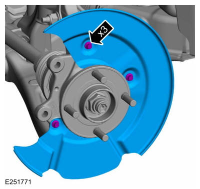
Removal and Installation - Brake Disc Shield
Removal
NOTE: Removal steps in this procedure may contain installation details.
Remove the brake disc.Refer to: Brake Disc (206-03 Front Disc Brake, Removal and Installation).
Remove the bolts and brake disc.
Torque: 80 lb.in (9 Nm)