Ford Ecosport: Power Brake Actuation / Removal and Installation - Brake Booster - LHD
Ford Ecosport 2014-2026 Service and Repair Manual / Brake System / Power Brake Actuation / Removal and Installation - Brake Booster - LHD
Removal
NOTE: Removal steps in this procedure may contain installation details.
-
Remove the battery tray.
Refer to: Battery Tray (414-01 Battery, Mounting and Cables, Removal and Installation).
-
Remove the brake master cylinder.
Refer to: Brake Master Cylinder (206-06 Hydraulic Brake Actuation, Removal and Installation).
-
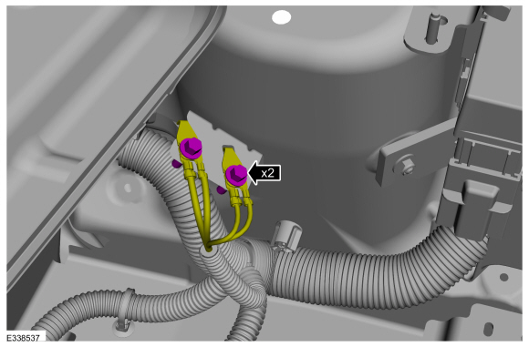
Remove the ground strap bolts.
Torque: 106 lb.in (12 Nm)
 |
-
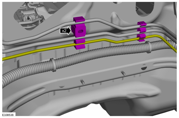
Position the brake line clip off of the bulkhead stud and release the lower brake line from the clips.
 |
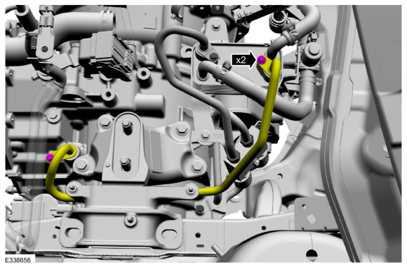
1.0L EcoBoost (92kW/125PS) (B7)
-
Remove the bolts and position aside the transmission cooler tube.
Torque: 97 lb.in (11 Nm)
 |
All vehicles
NOTICE: Do not service the brake pedal or brake booster without first removing the stoplamp switch. This switch must be removed with the brake pedal in the at-rest position. The switch plunger must be compressed for the switch to rotate in the bracket. Attempting to remove the switch when the plunger is extended (during pedal apply) will result in damage to the switch.
-
Remove the stoplamp switch.
Refer to: Stoplamp Switch (417-01 Exterior Lighting, Removal and Installation).
-
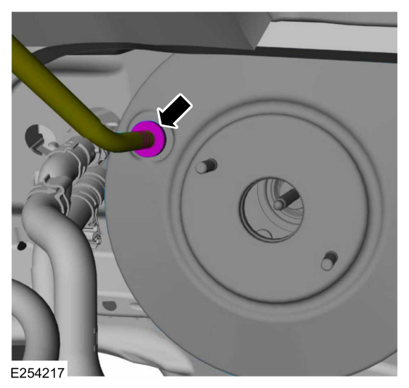
Detach the check valve from the brake booster.
 |
-
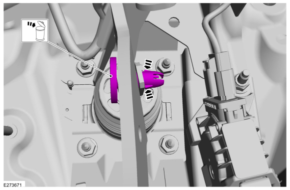
Press the tabs and remove the clevis pin. Discard the pin.
 |
-
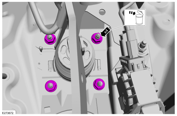
Remove and discard the brake booster nuts.
 |
-
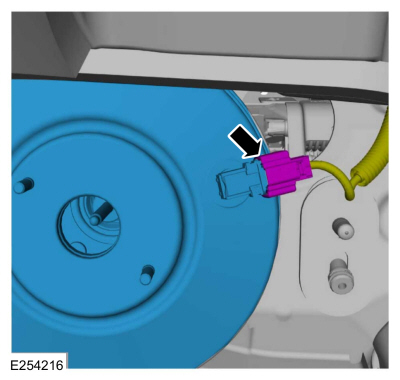
Disconnect the vacuum sensor electrical connector and remove the brake booster.
 |
Installation
NOTICE: Make sure that the brake booster pushrod is correctly located.
-
To install, reverse the removal procedure.
-
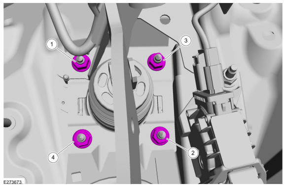
Install the brake booster and tighten the nuts in sequence.
Torque: 18 lb.ft (25 Nm)
 |


Other information:
Ford Ecosport 2014-2026 Service and Repair Manual: Diagnosis and Testing - Pinpoint Test - DTC: Y
U2300:55, U2300:64 Refer to Wiring Diagrams Cell 46 for schematic and connector information. NOTE: DTC U2300:55 is set in every new RCM installed until configuration data is successfully received from the BCM . Do not install any new components for this DTC unless directed to do so in the pinpoint test. Normal Operation and Fault Conditions On the first igni..
Ford Ecosport 2014-2026 Service and Repair Manual: Diagnosis and Testing - Transmission Cooling
Inspection and Verification Verify the customer concern. Visually inspect for obvious signs of mechanical or electrical damage. If an obvious cause for an observed or reported concern is found, correct the cause (if possible) before proceeding to the next step If the cause is not visually evident, verify the symptom and refer to the Symptom Chart...
Categories
- Manuals Home
- 2nd Gen Ford Ecosport Service Manual (2014 - 2026)
- Service Information
- Removal and Installation - Front Seat
- Description and Operation - Evaporative Emissions - System Operation and Component Description
- Removal and Installation - Rear Bumper
- Diagnosis and Testing - Body Control Module (BCM)
Removal and Installation - Oil Pressure Switch
Materials
Name Specification Motorcraft® Thread Sealant with PTFETA-24-B WSK-M2G350-A2
Removal
NOTE: Removal steps in this procedure may contain installation details.
With the vehicle in NEUTRAL, position it on a hoist.Refer to: Jacking and Lifting - Overview (100-02 Jacking and Lifting, Description and Operation).
If equipped, remove the bolts and the underbody shield.
Copyright © 2026 www.foecosport2.com