Ford Ecosport: Transfer Case - 6-Speed Automatic Transmission – 6F35 / Installation - Transfer Case
-
Install the new input seal RH .
Refer to: Transfer Case Input Shaft Seal RH (308-07B Transfer Case - 6-Speed Automatic Transmission – 6F35, Removal and Installation).
-
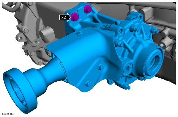
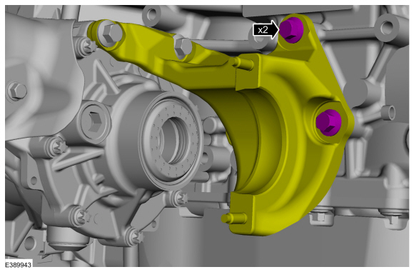
Install the PTU and the PTU mounting bolts.
Torque: 59 lb.ft (80 Nm)
 |
-
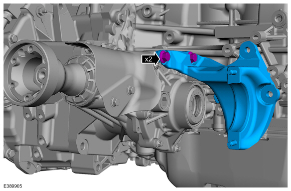
Install the engine mounting bracket and bolts.
Torque: 35 lb.ft (48 Nm)
 |
-
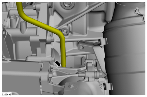
Connect PTU vent hose.
 |
-
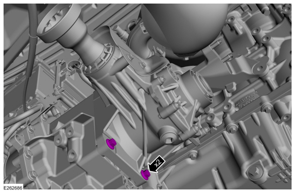
Install the PTU mounting bolts.
Torque: 59 lb.ft (80 Nm)
 |
-
Install the PTU to engine mounting bracket bolts.
Torque: 35 lb.ft (48 Nm)
 |
-
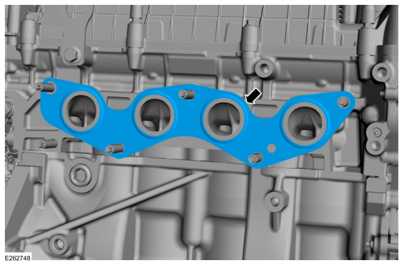
NOTE: Make sure the new gasket is installed.
-
Install the new gasket.
-
Install the new gasket.
 |
-
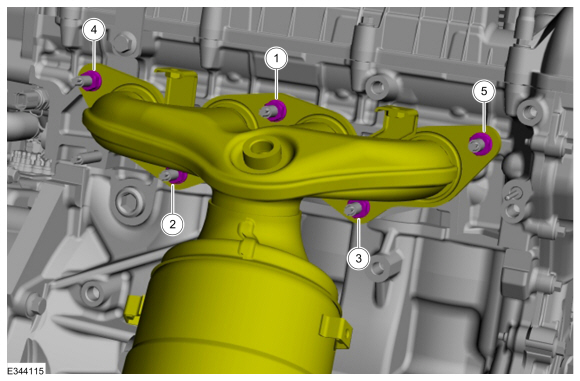
NOTE: Tighten the catalytic converter bolts in this sequence.
-
Position the catalytic converter and install the nuts.
Torque: 177 lb.in (20 Nm)
- Torque: 41 lb.ft (55 Nm)
-
Position the catalytic converter and install the nuts.
 |
-
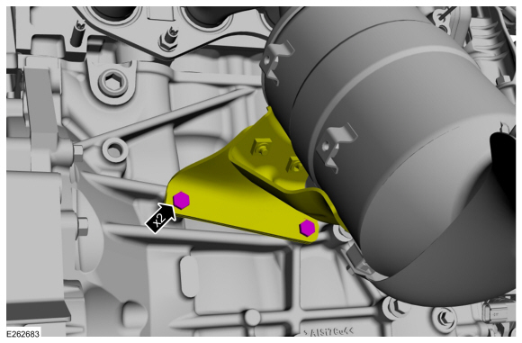
Install the bolt and position back catalytic converter mounting bracket.
Torque: 35 lb.ft (48 Nm)
 |
-
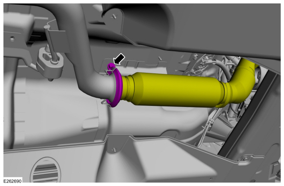
Position the pipe and install the new catalytic converter flange clamp.
Torque: 18 lb.ft (25 Nm)
 |
-
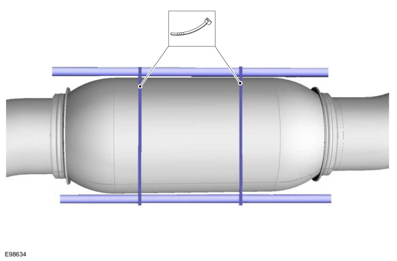
NOTICE: Make sure the exhaust flexible pipe is not forcibly bent or twisted.
Position back the flex pipe and release the cable ties.
 |
-
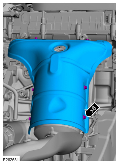
Install the catalytic converter shield and bolts.
Torque: 80 lb.in (9 Nm)
 |
-
Install the catalyst monitor sensor.
Refer to: Catalyst Monitor Sensor (303-14C Electronic Engine Controls - 2.0L Duratec-HE (129kW/175PS), Removal and Installation).
-
Install the HO2S .
Refer to: Heated Oxygen Sensor (HO2S) (303-14C Electronic Engine Controls - 2.0L Duratec-HE (129kW/175PS), Removal and Installation).
-
Install the rear driveshaft.
Refer to: Driveshaft (205-01 Driveshaft, Removal and Installation).
-
Install the RH front halfshaft.
Refer to: Front Halfshaft RH - 2.0L Duratec-HE (125kW/170PS) – MI4, AWD (205-04 Front Drive Halfshafts, Removal and Installation).
-
Start the Engine and check exhaust system for leaks.
-
Check the Transfer Case Fluid Level.
Refer to: Transfer Case Fluid Level Check (308-07B Transfer Case - 6-Speed Automatic Transmission – 6F35, General Procedures).
-
Refer to: Health and Safety Precautions (100-00 General Information, Description and Operation).
 Removal - Transfer Case
Special Tool(s) /
General Equipment
Cable Ties
Refer to: Health and Safety Precautions (100-00 General Information, Description and Operation)...

Other information:
Ford Ecosport 2014-2025 Service and Repair Manual: Diagnosis and Testing - Fuel System
General Equipment Ford diagnostic equipment DTC Charts: Diagnostics in this manual assume a certain skill level and knowledge of Ford-specific diagnostic practices. For information about these practices, REFER to: Diagnostic Methods (100-00 General Information, Description and Operation). PCM DTC Chart: DTC Desc..
Ford Ecosport 2014-2025 Service and Repair Manual: Removal and Installation - Audio Unit Antenna
Removal Lower the headliner. Refer to: Headliner - Lowering (501-05 Interior Trim and Ornamentation, Removal and Installation). Remove the audio unit antenna. Disconnect the antenna cable. Remove the audio unit antenna base bolt. Remove the audio unit antenna retaining bracket. ..
Categories
- Manuals Home
- 2nd Gen Ford Ecosport Service Manual (2014 - 2025)
- Body and Paint
- Removal and Installation - Rear Bumper
- Engine
- Climate Control System - General Information
- Service Information
Removal and Installation - Oil Pressure Switch
Materials
Name Specification Motorcraft® Thread Sealant with PTFETA-24-B WSK-M2G350-A2
Removal
NOTE: Removal steps in this procedure may contain installation details.
With the vehicle in NEUTRAL, position it on a hoist.Refer to: Jacking and Lifting - Overview (100-02 Jacking and Lifting, Description and Operation).
If equipped, remove the bolts and the underbody shield.
Copyright © 2025 www.foecosport2.com