Ford Ecosport: Supplemental Restraint System / General Procedures - Clockspring Adjustment
Special Tool(s) / General Equipment
| Adhesive Tape |
 WARNING:
If the clockspring is not correctly centralized, it may fail
prematurely. If in doubt, repeat the centralizing procedure. Failure to
follow these instructions may increase the risk of serious personal
injury or death in a crash.
WARNING:
If the clockspring is not correctly centralized, it may fail
prematurely. If in doubt, repeat the centralizing procedure. Failure to
follow these instructions may increase the risk of serious personal
injury or death in a crash.
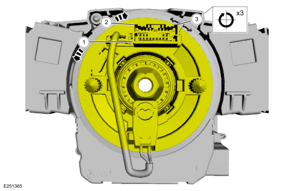
NOTE: Typical SCCM and clockspring shown, others similar.
-
Refer to: Pyrotechnic Device Health and Safety Precautions (100-00 General Information, Description and Operation).
WARNING:
Before beginning any service procedure in this section,
refer to Safety Warnings in section 100-00 General Information. Failure
to follow this instruction may result in serious personal injury.
-
NOTICE: Do not over-rotate the clockspring inner rotor. The internal ribbon wire is connected to the clockspring rotor. The internal ribbon wire acts as a stop and can be broken from its internal connection. Failure to follow this instruction may result in component damage and/or system failure.
-
Turn the clockspring rotor counterclockwise, carefully feeling for resistance to turning.
-
Turn the clockspring rotor clockwise so the electrical connector is in the 12 o'clock position.
-
NOTE: After final positioning, do not allow the clockspring rotor to rotate from this position.
Turn the clockspring rotor clockwise through 3 complete turns ending with the clockspring rotor electrical connector in the 12 o'clock position.
-
Turn the clockspring rotor counterclockwise, carefully feeling for resistance to turning.
 |
-
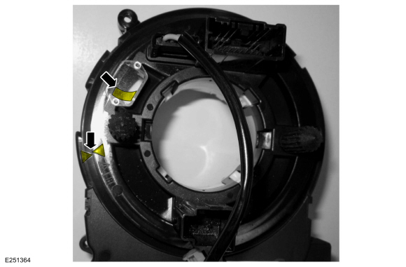
When the clockspring is correctly centralized, the wire
harness is visible through the site glass and the 2 arrows at the LH
side are aligned. Make sure the clockspring does not rotate from this
position until after the steering wheel is installed.
 |
-
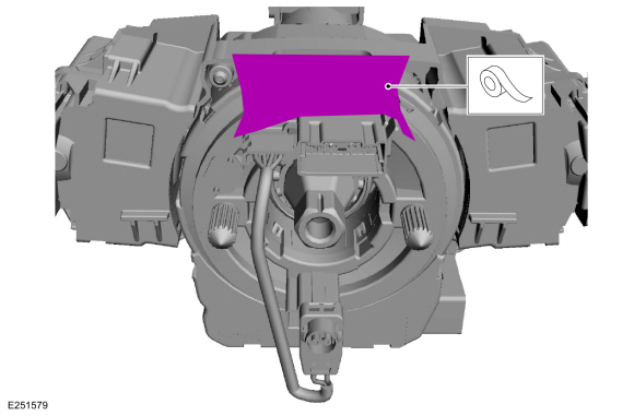
Tape the clockspring rotor to the outer housing to keep it from rotating.
Use the General Equipment: Adhesive Tape
 |

 General Procedures - Inspection and Repair after a Supplemental Restraint System (SRS) Deployment
Inspection
WARNING:
If a vehicle has been in a crash, inspect the Restraints
Control Module (RCM) and impact sensor mounting areas for any damage or
deformation...
Other information:
Ford Ecosport 2014-2025 Service and Repair Manual: General Procedures - Heater Core Leak Check - Vehicles With: R1234YF Refrigerant
Inspection NOTE: A coolant leak in the heater hose could follow the heater core tube to the heater core and appear as a leak in the heater core. Inspect for evidence of coolant leakage at the heater hose to heater core attachments...
Ford Ecosport 2014-2025 Service and Repair Manual: Diagnosis and Testing - Fuel Tank and Lines
Diagnostic Trouble Code (DTC) Chart Diagnostics in this manual assume a certain skill level and knowledge of Ford-specific diagnostic practices. REFER to: Diagnostic Methods (100-00 General Information, Description and Operation). Module DTC Description Action PCM P008A:00 Low Pressure Fuel System Pressure - Too Low: No Sub Type Information GO to Pinpoint Test HC ..
Categories
- Manuals Home
- 2nd Gen Ford Ecosport Service Manual (2014 - 2025)
- Removal and Installation - Evaporative Emission Canister Purge Valve
- Automatic Transmission - 6-Speed Automatic Transmission – 6F35
- Engine
- Removal and Installation - Body Control Module (BCM)
- Removal and Installation - Rear Bumper
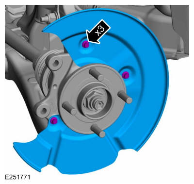
Removal and Installation - Brake Disc Shield
Removal
NOTE: Removal steps in this procedure may contain installation details.
Remove the brake disc.Refer to: Brake Disc (206-03 Front Disc Brake, Removal and Installation).
Remove the bolts and brake disc.
Torque: 80 lb.in (9 Nm)