Ford Ecosport: Rear View Mirrors / Diagnosis and Testing - Rear View Mirrors
Refer to Wiring Diagrams Cell 124 for schematic and connector information.
Symptom Chart(s)
Symptom Chart: Rear View Mirrors - Exterior
Diagnostics in this manual assume a certain skill level and knowledge of Ford-specific diagnostic practices.
NOTE: Clean the entire mirror assembly and glass to assist in verification of the customer concern and/or impact damage. Do not clean any mirror glass or housing with an ice scraper, razor blade, abrasive pad, harsh chemicals or petroleum based cleaning products, as these may damage the mirror glass and/or housing.
| Condition | Possible Causes | Action |
| One or both exterior mirror(s) fold inward due to wind pressure | Mirror structural bracket is damaged |
INSPECT the mirror for structural damage. If necessary, INSTALL a new mirror. REFER to: Exterior Mirror (501-09 Rear View Mirrors, Removal and Installation). |
| The LH or RH exterior mirror selection switch LED is inoperative (exterior mirror selection switch functions normally) | Exterior mirror selection switch |
INSTALL a new front door window control switch. REFER to: Driver Door Window Control Switch (501-11 Glass, Frames and Mechanisms, Removal and Installation). |
| Both exterior rear view mirrors are inoperative | Refer to Pinpoint Test | GO to Pinpoint Test A |
| A single exterior rear view mirror is inoperative | Refer to Pinpoint Test | GO to Pinpoint Test B |
| A single exterior rear view mirror does not operate correctly with switch logic | Refer to Pinpoint Test | GO to Pinpoint Test C |
| Both exterior mirrors are inoperative |
|
|
| One or both heated exterior mirrors are inoperative | Refer to the Pinpoint Test | GO to Pinpoint Test D |
| Both heated exterior mirrors are always on | Refer to the Pinpoint Test |
DIAGNOSE the rear window defrost system. REFER to: Glass, Frames and Mechanisms (501-11 Glass, Frames and Mechanisms, Diagnosis and Testing). |
| The LH or RH heated exterior mirrors do not defrost at the same rate | Normal operation of the heated exterior mirror | No action required, the system is operating correctly at this time. |
| The exterior mirror turn indicator is inoperative or always on |
|
REFER to: Turn Signal and Hazard Lamps (417-01) . |
| The Blind Spot Information System (BLIS®) indicator is inoperative or always on (if equipped) |
|
REFER to: Blind Spot Information System (419-04) . |
Symptom Chart: Rear View Mirrors - Interior
Diagnostics in this manual assume a certain skill level and knowledge of Ford-specific diagnostic practices.
NOTE: Clean the entire mirror assembly and glass to assist in verification of the customer concern and/or impact damage. Do not clean any mirror glass or housing with an ice scraper, razor blade, abrasive pad, harsh chemicals or petroleum based cleaning products, as these may damage the mirror glass and/or housing.
| Condition | Possible Causes | Action |
| The interior mirror is blemished | Interior mirror glass/housing is dirty | CLEAN the affected interior mirror surface. |
| The interior mirror is damaged |
INSPECT the interior mirror damage. If needed, INSTALL a new interior rear view mirror. REFER to: Exterior Mirror (501-09 Rear View Mirrors, Removal and Installation). |
|
| The interior mirror vibrates or is loose | Interior mirror mounting loose |
If the mirror is still on the windshield, do not remove.
ATTEMPT to fully seat the mirror first. If the mirror is still loose or
vibrates, REMOVE and REINSTALL the mirror. If the condition still
exists, INSTALL a new interior mirror. REFER to: Interior Rear View Mirror (501-09 Rear View Mirrors, Removal and Installation). |
| The interior auto-dimming mirror does not operate correctly | Refer to the Pinpoint Test | GO to Pinpoint Test E |
Symptom Chart: Rear View Mirrors - Exterior NVH
Diagnostics in this manual assume a certain skill level and knowledge of Ford-specific diagnostic practices.
NOTE: Clean the entire mirror assembly and glass to assist in verification of the customer concern and/or impact damage. Do not clean any mirror glass or housing with an ice scraper, razor blade, abrasive pad, harsh chemicals or petroleum based cleaning products, as these may damage the mirror glass and/or housing.
| Condition | Possible Causes | Action |
| Exterior mirror housing vibrates or is loose |
|
TIGHTEN the exterior mirror mounting nuts. REFER to: Exterior Mirror (501-09 Rear View Mirrors, Removal and Installation). |
|
If possible, REMOVE the aftermarket parts and ROAD TEST the vehicle. If the concern is no longer present, ADVISE the customer that the aftermarket components were causing the undesired vibration. | |
| Exterior mirror glass vibrates or is loose |
|
PRESS the center of the exterior mirror
glass up, down, left and right to make sure the exterior mirror glass
is seated correctly. If the exterior mirror glass is still loose, REMOVE
the exterior mirror glass. INSPECT the exterior mirror backing plate
for damage. INSPECT the exterior mirror motor mounting screws and
TIGHTEN if necessary. If the exterior mirror backing plate is damaged,
INSTALL a new exterior mirror glass. REFER to: Exterior Mirror (501-09 Rear View Mirrors, Removal and Installation). |
| Wind noise | Foam gasket between exterior mirror housing and door is misaligned or damaged |
VERIFY the gasket is in good condition.
If necessary, REPOSITION the gasket between the exterior mirror housing
and the door. The foam gasket is not serviceable and if it cannot be
repaired, INSTALL a new exterior mirror. REFER to: Exterior Mirror (501-09 Rear View Mirrors, Removal and Installation). |
| Exterior mirror is not correctly fitted to the door |
VERIFY there are no gaps between the
exterior mirror and the door. If necessary, LOOSEN the exterior mirror
nuts and REPOSITION the exterior mirror as necessary. REFER to: Exterior Mirror (501-09 Rear View Mirrors, Removal and Installation). |
|
| Exterior mirror impact damage | INSPECT the exterior mirror to ensure that there is no damage to the housing or glass. |
Pinpoint Tests
 PINPOINT TEST A: BOTH EXTERIOR MIRRORS ARE INOPERATIVE
 |
Refer to Wiring Diagrams Cell 124 for schematic and connector information. Normal Operation and Fault Conditions The exterior mirror control switch receives voltage at all times from the CJB . The exterior mirror control switch has only one ground circuit. The exterior mirrors share a common circuit for both up/down and right/left movements. Possible Sources
NOTICE: Use the correct probe adapter(s) when making measurements. Failure to use the correct probe adapter(s) may damage the connector. |
||||||||||
| A1 CHECK FOR VOLTAGE TO THE EXTERIOR MIRROR CONTROL SWITCH | ||||||||||
Is the voltage greater than 11 volts?
|
||||||||||
| A2 CHECK FOR GROUND TO THE EXTERIOR MIRROR CONTROL SWITCH | ||||||||||
Is the resistance less than 3 ohms?
|
||||||||||
| A3 CHECK THE EXTERIOR MIRROR COMMON CIRCUIT FOR A SHORT TO VOLTAGE | ||||||||||
Is any voltage present?
|
||||||||||
| A4 CHECK THE EXTERIOR MIRROR COMMON CIRCUIT FOR A SHORT TO GROUND | ||||||||||
Is resistance to ground greater than 10,000 ohms?
|
||||||||||
| A5 CHECK THE EXTERIOR MIRROR COMMON CIRCUIT FOR AN OPEN | ||||||||||
Is the resistance less than 3 ohms?
|
 PINPOINT TEST B: A SINGLE REAR VIEW MIRROR IS INOPERATIVE
|
Refer to Wiring Diagrams Cell 124 for schematic and connector information. Normal Operation and Fault Conditions Each exterior mirror motor has specific circuits that control the down/up and left/right movement of the glass. The motors share a common return circuit. Possible Sources
NOTICE: Use the correct probe adapter(s) when making measurements. Failure to use the correct probe adapter(s) may damage the connector. |
||||||||||||||||
| B1 CHECK THE EXTERIOR MIRROR CONTROL SWITCH | ||||||||||||||||
Did the exterior mirror control switch pass the component test?
|
||||||||||||||||
| B2 CHECK THE INOPERATIVE MIRROR COMMON CIRCUIT FOR AN OPEN | ||||||||||||||||
Is the resistance less than 3 ohms?
|
 PINPOINT TEST C: A SINGLE MIRROR DOES NOT FUNCTION WITH SWITCH LOGIC
|
Refer to Wiring Diagrams Cell 124 for schematic and connector information. Normal Operation and Fault Conditions Under normal operation, the exterior mirror control switch supplies voltage and ground to the LH and RH exterior mirrors to control movement. Each mirror contains a horizontal and a vertical motor. The exterior mirror control switch controls movement by reversing polarity of the voltage and ground circuits being supplied to each motor. Possible Sources
NOTICE: Use the correct probe adapter(s) when making measurements. Failure to use the correct probe adapter(s) may damage the connector. |
||||||||||||||||
| C1 CHECK THE MIRROR MOVEMENT (LEFT/RIGHT) | ||||||||||||||||
Do both exterior mirrors move left and right?
|
||||||||||||||||
| C2 CHECK THE MIRROR MOVEMENT (UP/DOWN) | ||||||||||||||||
Do both exterior mirrors move up and down?
|
||||||||||||||||
| C3 CHECK THE VOLTAGE TO THE INOPERATIVE MIRROR LEFT/RIGHT CIRCUITS | ||||||||||||||||
Is the voltage greater than 11 volts?
|
||||||||||||||||
| C4 CHECK THE MIRROR CONTROL LEFT/RIGHT CIRCUITS FOR AN OPEN | ||||||||||||||||
Is the resistance less than 3 ohms?
|
||||||||||||||||
| C5 CHECK THE VOLTAGE TO THE INOPERATIVE MIRROR UP/DOWN CIRCUITS | ||||||||||||||||
Is the voltage greater than 11 volts?
|
||||||||||||||||
| C6 CHECK THE MIRROR CONTROL UP/DOWN CIRCUITS FOR AN OPEN | ||||||||||||||||
Is the resistance less than 3 ohms?
|
||||||||||||||||
| C7 CHECK THE HARNESS(ES) AND CONNECTORS | ||||||||||||||||
Were any concerns found?
|
 PINPOINT TEST D: ONE OR BOTH HEATED EXTERIOR MIRRORS ARE INOPERATIVE
 |
NOTE: Clean the entire mirror assembly and glass to assist in verification of the customer concern and/or impact damage. Do not clean any mirror glass or housing with an ice scraper, razor blade, abrasive pad, harsh chemicals or petroleum based cleaning products, as these may damage the mirror glass and/or housing. Refer to Wiring Diagrams Cell 124 for schematic and connector information. Refer to Wiring Diagrams Cell 56 for schematic and connector information. Normal Operation and Fault Conditions The heated exterior mirrors receive voltage from
the rear window defrost system. The heated exterior mirrors only operate
when the rear window defrost is on. REFER to: Glass, Frames and
Mechanisms - Overview (501-11 Glass, Frames and Mechanisms, Description
and Operation). Possible Sources
Visual Inspection and Pre-checks
|
||||||||||
| D1 CHECK THE OPERATION OF THE REAR WINDOW DEFROST SYSTEM | ||||||||||
Does the temperature of the rear window glass rise?
|
||||||||||
| D2 CHECK THE OPERATION OF THE HEATED EXTERIOR MIRRORS | ||||||||||
Does the temperature of at least one exterior mirror glass rise?
|
||||||||||
| D3 CHECK THE VOLTAGE TO THE LH (LEFT-HAND) HEATED EXTERIOR MIRROR GLASS | ||||||||||
Is the voltage greater than 11 volts?
|
||||||||||
| D4 CHECK THE LH (LEFT-HAND) EXTERIOR MIRROR GROUND CIRCUIT FOR AN OPEN | ||||||||||
Is the resistance less than 3 ohms?
|
||||||||||
| D5 CHECK THE VOLTAGE TO THE RH (RIGHT-HAND) HEATED EXTERIOR MIRROR GLASS | ||||||||||
Is the voltage greater than 11 volts?
|
||||||||||
| D6 CHECK THE RH (RIGHT-HAND) EXTERIOR MIRROR GROUND CIRCUIT FOR AN OPEN | ||||||||||
Is the resistance less than 3 ohms?
|
||||||||||
| D7 CHECK THE EXTERIOR MIRROR JUMPER HARNESS | ||||||||||
Is the harness OK?
|
 PINPOINT TEST E: THE INTERIOR AUTO-DIMMING MIRROR DOES NOT OPERATE CORRECTLY
|
Refer to Wiring Diagrams Cell 124 for schematic and connector information. Normal Operation and Fault Conditions
REFER to: Rear View Mirrors - System Operation and Component Description (501-09 Rear View Mirrors, Description and Operation). Possible Sources
Visual Inspection and Pre-checks
NOTICE: Use the correct probe adapter(s) when making measurements. Failure to use the correct probe adapter(s) may cause damage to the connector. Use only Rotunda Flex Probes (NUD105-R025D) |
||||||||||
| E1 VERIFY THE OPERATION OF THE REVERSE LAMPS | ||||||||||
Do the reverse lamps illuminate ONLY in REVERSE?
|
||||||||||
| E2 INSPECT THE MIRROR FOR PROPER INSTALLATION | ||||||||||
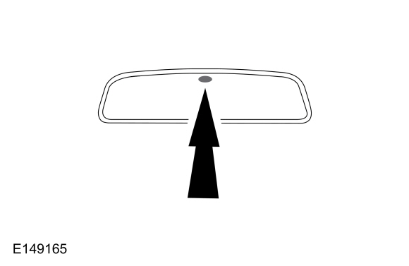
Is the rearward facing sensor at the top of the interior auto-dimming mirror glass?
|
||||||||||
| E3 VERIFY THE FORWARD AND REARWARD FACING SENSORS ARE NOT BLOCKED | ||||||||||
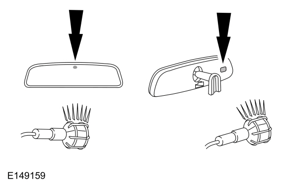
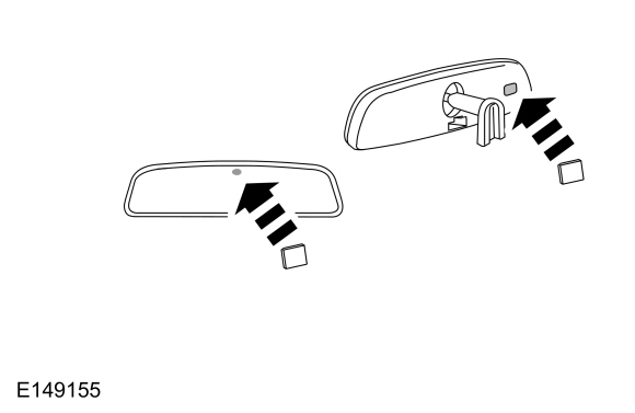
Are either of the sensors blocked?
|
||||||||||
| E4 VERIFY THE OPERATION OF THE INTERIOR AUTO-DIMMING MIRROR - DAYLIGHT CONDITIONS | ||||||||||
Did the mirror adjust to a high reflectance (clear) state?
|
||||||||||
| E5 VERIFY THE OPERATION OF THE INTERIOR AUTO-DIMMING MIRROR - NIGHTTIME CONDITIONS WITHOUT GLARE | ||||||||||
Did the mirror adjust to a high reflectance (clear) state?
|
||||||||||
| E6 VERIFY THE OPERATION OF THE INTERIOR AUTO-DIMMING MIRROR - NIGHTTIME CONDITIONS WITH GLARE | ||||||||||
Did the mirror adjust to a low reflectance (darkened) state?
|
||||||||||
| E7 VERIFY THE OPERATION OF THE INTERIOR AUTO-DIMMING MIRROR - VEHICLE IN REVERSE AND NIGHTTIME CONDITIONS WITH GLARE | ||||||||||
Did the mirror adjust to a high reflectance (clear) state after reverse was selected?
|
||||||||||
| E8 CHECK FOR VOLTAGE TO THE INTERIOR AUTO-DIMMING MIRROR | ||||||||||
Is the voltage greater than 11 volts?
|
||||||||||
| E9 CHECK FOR GROUND AT THE INTERIOR AUTO-DIMMING MIRROR | ||||||||||
Is the resistance less than 3 ohms?
|
||||||||||
| E10 CHECK FOR VOLTAGE TO THE INTERIOR AUTO-DIMMING MIRROR REVERSE INHIBIT CIRCUIT | ||||||||||
Is the voltage greater than 11 volts when reverse gear is selected and no voltage present when reverse gear is not selected?
|
 Description and Operation - Rear View Mirrors - System Operation and Component Description
System Operation
System Diagram - Exterior, Power
Item
Description
1
LH exterior mirror
2
Exterior mirror control switch
3
RH exterior mirror
System Operation - Exterior, Power
All
functions of the power mirror feature are integrated into one switch
module...
 Removal and Installation - Exterior Mirror
Special Tool(s) /
General Equipment
Flat Headed Screw Driver
Flat-Bladed Screwdriver
Removal
NOTE:
LH side shown, RH side similar...
Other information:
Ford Ecosport 2014-2025 Service and Repair Manual: Removal and Installation - Rear Seat Armrest
Removal NOTE: Removal steps in this procedure may contain installation details. Refer to: Rear Seat Backrest (501-10B Rear Seats, Removal and Installation). Release the seat backrest lower J-clip. On both sides...
Ford Ecosport 2014-2025 Service and Repair Manual: Removal and Installation - Transmission Range (TR) Sensor
Special Tool(s) / General Equipment Punch Locking Pliers Removal Remove the main control cover. Refer to: Main Control Cover (307-01B Automatic Transmission - 6-Speed Automatic Transmission – 6F35, Removal and Installation)...

 PINPOINT TEST A: BOTH EXTERIOR MIRRORS ARE INOPERATIVE


