Ford Ecosport: Supplemental Restraint System / Diagnosis and Testing - Pinpoint Test - DTC: Z, Vehicles With: Rear Seat Side Airbag
B140B:11, B140B:12, B140B:13, B140B:1A
Refer to Wiring Diagrams Cell 46 for schematic and connector information.
Normal Operation and Fault Conditions
The RCM continuously monitors the passenger second row side airbag circuits for the following faults:
- Resistance out of range
- Unexpected voltage
- Short to ground
- Faulted passenger second row side airbag
If a fault is detected, the RCM stores DTC B140B:11, B140B:12, B140B:13 or B140B:1A in memory and sends a message to the IPC to illuminate the airbag warning indicator.
The RCM analyzes the deployment loop resistance to determine if a fault exists. The value displayed in the PID is the deployment loop resistance measured by the RCM . If the value displayed is lower or higher than the desired range (refer to diagram below), the RCM can set a DTC . As the deployment loop resistance drifts farther outside the desired range, the chance for a DTC increases. Small variations in resistance can occur due to the effect of road vibrations on terminal fit. Crimps and terminals can be affected by stress and harness movement and can cause an increase in resistance due to wire strain. These variables can result in an intermittent fault. For this reason, the test requires the PID value to be within the desired range before the fault is considered repaired, regardless if the module is reporting an on-demand DTC at the time of diagnosis. Following this direction helps make sure that minor changes in resistance do not create a repeat concern. This test uses process of elimination to diagnose each part of the deployment loop circuit including:
- Wiring
- Connections
- Passenger second row side airbag
- RCM
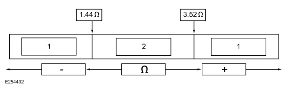
| Item | Description |
|---|---|
| 1 | May set DTC |
| 2 | Desired range |
DTC Fault Trigger Conditions
| DTC | Description | Fault Trigger Conditions |
|---|---|---|
| B140B:11 | Second Row Passenger Side Airbag Deployment Control: Circuit Short to Ground | A fault is indicated when the RCM senses a short to ground on either passenger second row side airbag circuit for more than 6 seconds. |
| B140B:12 | Second Row Passenger Side Airbag Deployment Control: Circuit Short to Battery | A fault is indicated when the RCM senses a short to voltage on either passenger second row side airbag circuit for more than 6 seconds. |
| B140B:13 | Second Row Passenger Side Airbag Deployment Control: Circuit Open | A fault is indicated when the RCM measures more than the desired resistance between the passenger second row side airbag circuits for more than 6 seconds. |
| B140B:1A | Second Row Passenger Side Airbag Deployment Control: Circuit Resistance Below Threshold | A fault is indicated when the RCM measures less than the desired resistance between the passenger second row side airbag circuits for more than 6 seconds. |
Possible Sources
- Wiring, terminals or connectors
- Passenger second row side airbag
- RCM
PINPOINT TEST A: B140B:11, B140B:12, B140B:13 AND B140B:1A
 WARNING:
Incorrect repair techniques or actions can cause an
accidental Supplemental Restraint System (SRS) deployment. Never
compromise or depart from these instructions. Failure to precisely
follow all instructions could result in serious personal injury from an
accidental deployment.
WARNING:
Incorrect repair techniques or actions can cause an
accidental Supplemental Restraint System (SRS) deployment. Never
compromise or depart from these instructions. Failure to precisely
follow all instructions could result in serious personal injury from an
accidental deployment.
|
|||||||||||||
| NOTICE: Use the correct probe adapter(s) when making measurements. Failure to use the correct probe adapter(s) may cause damage to the connector. | |||||||||||||
| NOTE: Most faults are due to connector and/or wiring concerns. Carry out a thorough inspection and verification before proceeding with the pinpoint test. | |||||||||||||
| NOTE: Only disconnect or reconnect SRS components when instructed to do so within a pinpoint test step. Failure to follow this instruction may result in incorrect diagnosis of the SRS . | |||||||||||||
| NOTE: Always make sure the correct SRS component is being installed. Parts released for other vehicles may not be compatible even if they appear physically similar. Check the part number listed in the Ford parts catalog to make sure the correct component is being installed. If an incorrect SRS component is installed, Diagnostic Trouble Codes (DTCs) may set. | |||||||||||||
| NOTE: The SRS must be fully operational and free of faults before releasing the vehicle to the customer. | |||||||||||||
| A1 RETRIEVE RCM (RESTRAINTS CONTROL MODULE) DIAGNOSTIC TROUBLE CODES (DTCS) | |||||||||||||
Was DTC B140B:11, B140B:12, B140B:13 and B140B:1A retrieved on-demand during self-test?
|
|||||||||||||
| A2 CHECK THE SECOND ROW PASSENGER SIDE AIRBAG DEPLOYMENT CONTROL (DEPLOY_17_R) PID (PARAMETER IDENTIFICATION) | |||||||||||||
Does the PID value read between 1.44 and 3.52 ohms?
|
|||||||||||||
| A3 CHECK THE SECOND ROW PASSENGER SIDE AIRBAG DEPLOYMENT CONTROL (DEPLOY_17_R) PID (PARAMETER IDENTIFICATION) WHILE CARRYING OUT THE HARNESS TEST | |||||||||||||
Does the PID value read between 1.44 and 3.52 ohms while carrying out the harness test?
|
|||||||||||||
| A4 CHECK THE PASSENGER SECOND ROW SIDE AIRBAG DEPLOYMENT CONTROL DTC (DIAGNOSTIC TROUBLE CODE) FOR A FAULT STATUS CHANGE (LOW RESISTANCE INDICATED) | |||||||||||||
|
NOTE: This pinpoint test step attempts to change the fault reported by the RCM by inducing a different fault condition. If the reported fault changes, this indicates the RCM is functioning correctly and is not the source of the fault.
Did the on-demand DTC change from B140B:1A to B140B:13?
|
|||||||||||||
| A5 CHECK FOR A SHORT BETWEEN THE PASSENGER SECOND ROW SIDE AIRBAG CIRCUITS | |||||||||||||
Is the resistance greater than 10,000 ohms?
|
|||||||||||||
| A6 CHECK THE PASSENGER SECOND ROW SIDE AIRBAG CIRCUITS FOR AN OPEN | |||||||||||||
Are the resistances less than 0.5 ohm?
|
|||||||||||||
| A7 CHECK THE PASSENGER SECOND ROW SIDE AIRBAG DEPLOYMENT CONTROL DTC (DIAGNOSTIC TROUBLE CODE) FOR A FAULT STATUS CHANGE (OPEN INDICATED) | |||||||||||||
|
NOTE: This pinpoint test step attempts to change the fault reported by the RCM by inducing a different fault condition. If the reported fault changes, this indicates the RCM is functioning correctly and is not the source of the fault.
Did the on-demand DTC change from B140B:13 to B140B:1A?
|
|||||||||||||
| A8 CHECK THE PASSENGER SECOND ROW SIDE AIRBAG DEPLOYMENT CONTROL DTC (DIAGNOSTIC TROUBLE CODE) FOR A FAULT STATUS CHANGE (SHORT TO GROUND INDICATED) | |||||||||||||
|
NOTE: This pinpoint test step attempts to change the fault reported by the RCM by inducing a different fault condition. If the reported fault changes, this indicates the RCM is functioning correctly and is not the source of the fault.
Did the on-demand DTC change from B140B:11 to B140B:13?
|
|||||||||||||
| A9 CHECK THE PASSENGER SECOND ROW SIDE AIRBAG CIRCUITS FOR A SHORT TO GROUND | |||||||||||||
Are the resistances greater than 10,000 ohms?
|
|||||||||||||
| A10 CHECK THE PASSENGER SECOND ROW SIDE AIRBAG CIRCUITS FOR A SHORT TO VOLTAGE | |||||||||||||
Is any voltage present?
|
|||||||||||||
| A11 CONFIRM THE PASSENGER SECOND ROW SIDE AIRBAG FAULT | |||||||||||||
|
NOTE: Make sure all SRS components and the RCM electrical connectors are connected before carrying out the self-test. If not, Diagnostic Trouble Codes (DTCs) are recorded.
Was the original DTC retrieved on-demand during self-test?
|
|||||||||||||
| A12 CONFIRM THE RCM (RESTRAINTS CONTROL MODULE) FAULT | |||||||||||||
|
NOTE: Make sure all SRS components and the RCM electrical connectors are connected before carrying out the self-test. If not, Diagnostic Trouble Codes (DTCs) are recorded.
Was the original DTC retrieved on-demand during self-test?
|
|||||||||||||
| A13 CHECK THE SECOND ROW PASSENGER SIDE AIRBAG DEPLOYMENT CONTROL (DEPLOY_17_R) PID (PARAMETER IDENTIFICATION) FOR AN INTERMITTENT LOW RESISTANCE OR OPEN CIRCUIT FAULT | |||||||||||||
Does the PID value read between 1.44 and 3.52 ohms?
|
|||||||||||||
| A14 CHECK THE PASSENGER SECOND ROW SIDE AIRBAG DEPLOYMENT CONTROL CIRCUITS FOR AN INTERMITTENT SHORT TO GROUND FAULT | |||||||||||||
Was DTC B140B:11 retrieved on-demand during self-test?
|
|||||||||||||
| A15 CHECK THE PASSENGER SECOND ROW SIDE AIRBAG DEPLOYMENT CONTROL CIRCUITS FOR AN INTERMITTENT SHORT TO BATTERY FAULT | |||||||||||||
Was DTC B140B:12 retrieved on-demand during self-test?
|
|||||||||||||
| A16 CHECK THE HARNESS AND CONNECTORS | |||||||||||||
Were any concerns found?
|
|||||||||||||
| A17 CHECK FOR ADDITIONAL SRS (SUPPLEMENTAL RESTRAINT SYSTEM) DIAGNOSTIC TROUBLE CODES (DTCS) | |||||||||||||
Are any RCM , OCSM and/or BECMB Diagnostic Trouble Codes (DTCs) retrieved on-demand during self-test?
|


 Diagnosis and Testing - Pinpoint Test - DTC: Y
U2300:55, U2300:64
Refer to Wiring Diagrams Cell 46 for schematic and connector information.
NOTE:
DTC U2300:55 is set in every new RCM installed until configuration data
is successfully received from the BCM ...
 Diagnosis and Testing - Pinpoint Test - DTC: AA, Vehicles With: Rear Seat Side Airbag
B1413:11, B1413:12, B1413:13, B1413:96
Refer to Wiring Diagrams Cell 46 for schematic and connector information.
Normal Operation and Fault Conditions
The RCM monitors the front impact severity sensor circuits for the following faults:
Open circuit
Short to voltage
Short to ground
Faulted front impact severity sensor
If a fault is detec..
Other information:
Ford Ecosport 2014-2024 Service and Repair Manual: General Procedures - Cylinder Block Core Plug Replacement
Special Tool(s) / General Equipment 100-001 (T50T-100-A) Slide Hammer Materials Name Specification Motorcraft® Threadlock 262TA-26 WSK-M2G351-A6 Repair All core plugs NOTE: Cylinder block core plug shown, cylinder head core plug similar. Using the Slide Hammer and a commercially available body dent puller att..
Ford Ecosport 2014-2024 Service and Repair Manual: Description and Operation - Front Seats - System Operation and Component Description
System Operation Heated Seats The driver and passenger heated seat control buttons and indicators are located on the HVAC module. The heated seat system functions independently from the climate control system. Each time the heated seat button is pressed, the HVAC module decreases one setting (the sequence is high, medium, low, off, high, etc.). When a heated seat is set to high, a..
Categories
- Manuals Home
- 2nd Gen Ford Ecosport Service Manual (2014 - 2024)
- General Procedures - Transmission Fluid Level Check
- Automatic Transmission - 6-Speed Automatic Transmission – 6F35
- Body and Paint
- Removal and Installation - Catalytic Converter
- Removal and Installation - Fuel Filler Door Assembly
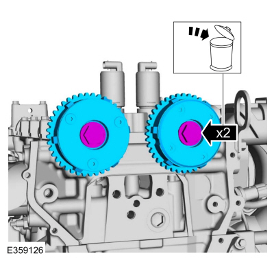
Removal and Installation - Variable Camshaft Timing (VCT) Unit
Removal
NOTICE: During engine repair procedures, cleanliness is extremely important. Any foreign material, including any material created while cleaning gasket surfaces, that enters the oil passages, coolant passages or the oil pan can cause engine failure.
Remove the timing chain.Refer to: Timing Chain (303-01C Engine - 2.0L Duratec-HE (129kW/175PS), Removal and Installation).
Remove the bolts and VCT units.
Discard the bolts.