Ford Ecosport: Four-Wheel Drive Systems / Diagnosis and Testing - Four-Wheel Drive Systems
DTC Chart: AWD System - PCM
Diagnostics in this manual assume a certain skill level and knowledge of Ford-specific diagnostic practices.
REFER to: Diagnostic Methods (100-00 General Information, Description and Operation).
Network DTC
s (U-codes) are often a result of intermittent concerns such as damaged
wiring or low battery voltage occurrences. Additionally, vehicle repair
procedures, such as module reprogramming, often set network DTC s.
Replacing a module to resolve a network DTC is unlikely to resolve the
concern. To prevent repeat network DTC concerns, inspect all network
wiring, especially connectors. Test the vehicle battery.
REFER to: Battery (414-01 Battery, Mounting and Cables, Diagnosis and Testing).
DTC Chart - PCM
| DTC | Description | Action |
| P164D | AWD ID Block Corrupted, Not Programmed |
PROGRAM the PCM with the Active Torque Coupling (ATC) solenoid bar code
information using Automatic Torque Coupling Configuration. REFER to: Four-Wheel Drive Systems - System Operation and Component Description (308-07A Four-Wheel Drive Systems, Description and Operation). |
| P181F | Clutch Control System Performance |
This is an internal AWD relay module fault. INSTALL a new AWD relay module. REFER to: All-Wheel Drive (AWD) Module (308-07A Four-Wheel Drive Systems, Removal and Installation). |
| P187B | Tire Size Out of Acceptable Range - AWD Disabled / Limited Function | GO to Pinpoint Test B |
| P188B | AWD Clutch Control Circuit | GO to Pinpoint Test C |
| P188C | AWD Relay Module Communication Circuit | CLEAR the DTC s. REPEAT the self-test. If the DTC returns, GO to Pinpoint Test D |
| P188D | AWD Relay Module Feedback Circuit | CLEAR the DTC s. REPEAT the self-test. If the DTC returns, GO to Pinpoint Test D |
Symptom Chart
Diagnostics in this manual assume a certain skill level and knowledge of Ford-specific diagnostic practices.
REFER to: Diagnostic Methods (100-00 General Information, Description and Operation).
In most circumstances, the PCM sets DTC s to help guide with diagnostics. Refer to the DTC Chart before using the symptom chart. The Symptom column lists the vehicle condition. The Possible Sources column lists a detailed vehicle condition. The Action column lists the action to be performed to determine the cause of the condition. Each action lists the components that can cause the system and the individual components in that system. The components are listed in order of disassembly. Use the list of components and the required action to focus on disassembly inspections for the root cause of the concern.
Symptom Chart - Four-Wheel Drive Systems
| Condition | Possible Sources | Actions |
|---|---|---|
| Unable to duplicate customer concern; no DTC present | The concern description is inaccurate | CARRY OUT the AWD System Functional Test. GO to Pinpoint Test A |
| Vehicle has no or inadequate torque at rear wheels |
|
GO to Pinpoint Test C |
| Wheels/tires |
Check wheels and tires for damage. REFER to: Wheels and Tires (204-04A Wheels and Tires, Diagnosis and Testing). |
|
| Rear axle |
Check rear axle for damage. REFER to: Rear Drive Axle and Differential (205-02 Rear Drive Axle/Differential, Diagnosis and Testing). |
|
| PTU mechanical failure |
Check PTU for damage. REFER to: Transfer Case (308-07B Transfer Case - 6-Speed Automatic Transmission – 6F35, Diagnosis and Testing). |
|
| Vehicle binds in a turn or resists turning/pulsates or shudders in a straight line | Wheels/tires |
Check wheels and tires for damage. REFER to: Wheels and Tires (204-04A Wheels and Tires, Diagnosis and Testing). |
| Wiring, terminals or connectors | GO to Pinpoint Test E | |
| Driveshaft |
Check driveshaft for damage. REFER to: Driveshaft (205-01 Driveshaft, Diagnosis and Testing). |
|
|
GO to Pinpoint Test E | |
| PTU mechanical failure |
Check PTU for damage. REFER to: Transfer Case (308-07B Transfer Case - 6-Speed Automatic Transmission – 6F35, Diagnosis and Testing). |
|
| Driveshaft |
Check driveshaft for damage. REFER to: Suspension System - AWD (204-00 Suspension System - General Information, Diagnosis and Testing). |
|
| Wheel bearings |
Check wheel bearings for damage. REFER to: Suspension System - AWD (204-00 Suspension System - General Information, Diagnosis and Testing). |
|
| ABS |
CHECK the ABS . REFER to: Anti-Lock Brake System (ABS) and Stability Control (206-09 Anti-Lock Brake System (ABS) and Stability Control, Diagnosis and Testing). |
|
| Halfshafts |
Check the halfshafts for damage. REFER to: Rear Drive Halfshafts (205-05 Rear Drive Halfshafts, Diagnosis and Testing). |
|
| Tire/axle out of acceptable range |
|
GO to Pinpoint Test B |
Pinpoint Tests
|
Normal Operation and Fault Conditions The AWD system is an active system, which means it not only responds to wheel slip between the front and rear axles but also has the ability to anticipate wheel slip and transfer torque to the rear wheels before the slip occurs. The AWD system is active all the time and requires no input from the operator. The AWD system continuously monitors vehicle conditions and automatically adjusts the torque distribution between the front and rear wheels. During normal operation, most of the torque is delivered to the front wheels. If wheel slip between the front and rear wheels is detected, if the vehicle is under acceleration or if the vehicle is in a handling event, the AWD system increases and distributes torque to the rear wheels as needed. When the AWD system is functioning properly, there should be no perceived speed difference between the front and rear axles when launching or driving the vehicle on any uniform surface. Traction should be similar to a part time 4WD system in 4H (4X4 HIGH), but have no binding in turns. Possible Sources
Visual Inspection and Pre-checks
NOTE: Check related modules for Diagnostic Trouble Codes (DTCs). If Diagnostic Trouble Codes (DTCs) are set in other modules, diagnose those Diagnostic Trouble Codes (DTCs) first before continuing. |
||||
| A1 CHECK FOR ACTIVE TORQUE COUPLING SOLENOID LOCK | ||||
Is driveline wind-up present in turns?
|
||||
| A2 CHECK ABS WHEEL SPEEDS | ||||
Are all 4 wheel speeds within 1.2 mph ( 2 km/h) of each other?
|
||||
| A3 CHECK VEHICLE ACCELERATION IN A STRAIGHT LINE | ||||
Does the vehicle pulsate or shudder while accelerating?
|
||||
| A4 CHECK VEHICLE TURNING ABILITY | ||||
Does the vehicle bind in the turn or resist turning?
|
||||
| A5 CHECK TORQUE AT THE REAR WHEELS | ||||
Does the vehicle bind in the turn or resist turning?
|
 WARNING:
When directed to drive the vehicle as part of this test,
drive the vehicle on a hard surface in an area without traffic to
prevent a crash. Failure to follow these instructions may result in
personal injury.
WARNING:
When directed to drive the vehicle as part of this test,
drive the vehicle on a hard surface in an area without traffic to
prevent a crash. Failure to follow these instructions may result in
personal injury.
|
Normal Operation and Fault Conditions The AWD system uses input data from the ABS module wheel speed sensor inputs to the PCM . A dissimilar spare tire size (other than the spare tire provided) or major dissimilar tire sizes or improperly inflated tires between the front and rear axles could cause the AWD system to stop functioning correctly. DTC Fault Trigger Conditions
Possible Sources
Visual Inspection and Pre-checks
|
||||||
| B1 CHECK FOR RECENT DIFFERENT SIZED TIRE USAGE | ||||||
Was a tire recently installed on the vehicle that was not originally supplied with the vehicle or has the mini spare been used?
|
||||||
| B2 CHECK TIRE SIZE AND BRAND | ||||||
Are all 4 tires the same size and brand?
|
||||||
| B3 CHECK TIRE AIR PRESSURES | ||||||
Are all 4 tires at the recommended air pressure?
|
||||||
| B4 CHECK ABS WHEEL SPEEDS | ||||||
Are all 4 wheel speeds within 1.2 mph ( 2 km/h) of each other?
|
||||||
| B5 CHECK FOR CORRECT ABS AND AWD (ALL-WHEEL DRIVE) SYSTEM OPERATION | ||||||
Is the concern still present?
|
|
Refer to Wiring Diagrams Cell 34 for schematic and connector information. Normal Operation and Fault Conditions The AWD system uses data from other systems as inputs to the PCM . The PCM uses the inputs to determine the appropriate time to send a signal and have the AWD relay module energize the Active Torque Coupling (ATC) solenoid. DTC Fault Trigger Conditions
Possible Sources
Visual Inspection and Pre-checks
|
|||||||||||||
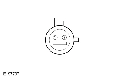
| C1 CHECK THE ACTIVE TORQUE COUPLING SOLENOID | |||||||||||||
Is the resistance between 1 and 5 ohms?
|
|||||||||||||
| C2 CHECK THE ATC SOLENOID CIRCUITS FOR AN OPEN | |||||||||||||
Is the resistance less than 3 ohms?
|
|||||||||||||
| C3 CHECK THE ACTIVE TORQUE COUPLING SOLENOID CIRCUITS FOR A SHORT TO GROUND | |||||||||||||
Is the resistance greater than 10,000 ohms?
|
|||||||||||||
| C4 CHECK THE ATC SOLENOID CIRCUITS FOR A SHORT TOGETHER | |||||||||||||
Is the resistance greater than 10,000 ohms?
|
|||||||||||||
| C5 CHECK THE ATC SOLENOID CIRCUITS FOR A SHORT TO POWER | |||||||||||||
Is any voltage detected?
|
|||||||||||||
| C6 CHECK THE ATC SOLENOID | |||||||||||||
Is the resistance between 1 to 5 ohms?
|
|||||||||||||
| C7 CHECK FOR CORRECT PCM (POWERTRAIN CONTROL MODULE) OPERATION | |||||||||||||
Is the concern still present?
|


 C4347-1
 Click here to access Guided Routine (PCM).
|
Refer to Wiring Diagrams Cell 34 for schematic and connector information. Normal Operation and Fault Conditions The AWD system uses data from other systems as inputs to the PCM . The PCM uses the inputs to determine the appropriate time to send a signal to the AWD relay module to energize the Active Torque Coupling (ATC) solenoid. The PCM communicates this signal on the AWDC or AWD Command circuit. The AWD relay module provides feedback on the AWDM or All wheel drive monitor circuit. DTC Fault Trigger Conditions
Possible Sources
Visual Inspection and Pre-checks
|
|||||||||||||
| D1 CHECK THE AWD (ALL-WHEEL DRIVE) RELAY VOLTAGE CIRCUIT | |||||||||||||
|
NOTE: Fuse 9 (5A) protects multiple components. Check related systems that may be inoperative.
Is the voltage greater than 11 volts?
|
|||||||||||||
| D2 CHECK THE AWD (ALL-WHEEL DRIVE) RELAY MODULE GROUND CIRCUIT FOR AN OPEN | |||||||||||||
Is the voltage greater than 11 volts?
|
|||||||||||||
| D3 CHECK THE AWD (ALL-WHEEL DRIVE) RELAY MODULE COMMAND AND FEEDBACK CIRCUITS FOR A SHORT TO VOLTAGE | |||||||||||||
Is any voltage present?
|
|||||||||||||
| D4 CHECK THE AWD (ALL-WHEEL DRIVE) RELAY MODULE COMMAND AND FEEDBACK CIRCUITS FOR A SHORT TO GROUND | |||||||||||||
Is the resistance greater than 10,000 ohms?
|
|||||||||||||
| D5 CHECK THE AWD (ALL-WHEEL DRIVE) RELAY MODULE COMMAND AND FEEDBACK CIRCUITS FOR AN OPEN | |||||||||||||
Is the resistance less than 3 ohms?
|
|||||||||||||
| D6 CHECK THE AWD (ALL-WHEEL DRIVE) RELAY MODULE COMMAND AND FEEDBACK CIRCUITS FOR A SHORT TOGETHER | |||||||||||||
Is the resistance greater than 10,000 ohms?
|
|||||||||||||
| D7 CHECK FOR CORRECT PCM (POWERTRAIN CONTROL MODULE) OPERATION | |||||||||||||
Did DTC P188C or P188D reset?
|
|
Refer to Wiring Diagrams Cell 34 for schematic and connector information. Normal Operation and Fault Conditions The AWD system is an active system, which means it not only responds to wheel slip between the front and rear axles but also has the ability to anticipate wheel slip and transfer torque to the rear wheels before the slip occurs. The AWD system is active all the time and requires no input from the operator. The AWD system continuously monitors vehicle conditions and automatically adjusts the torque distribution between the front and rear wheels. During normal operation, most of the torque is delivered to the front wheels. If wheel slip between the front and rear wheels is detected, if the vehicle is under acceleration or if the vehicle is in a handling event, the AWD system increases and distributes torque to the rear wheels as needed. When the AWD system is functioning properly, there should be no perceived speed difference between the front and rear axles when launching or driving the vehicle on any uniform surface. Traction should be similar to a part time 4WD system in 4H (4X4 HIGH), but have no binding in turns. Possible Sources
Visual Inspection and Pre-checks
|
||||
| E1 CHECK FOR TORQUE AT THE REAR WHEELS | ||||
Is a pulsation or shudder still present?
|
||||
| E2 MONITOR THE CLUTCH STATUS PID | ||||
Is the duty cycle greater than 20%?
|
||||
| E3 CHECK FOR THE CORRECT WHEEL SPEEDS | ||||
Are all 4 wheel speeds within 1.2 mph ( 2 km/h) of each other?
|
||||
| E4 CHECK FOR CORRECT AWD (ALL-WHEEL DRIVE) RELAY MODULE OPERATION | ||||
Is the concern still present?
|
 Description and Operation - Four-Wheel Drive Systems - System Operation and Component Description
S..
 Removal and Installation - All-Wheel Drive (AWD) Module
Removal
NOTE:
Removal steps in this procedure may contain installation details.
NOTE:
Position aside the RH side front seat
Move the seat to back position...
Other information:
Ford Ecosport 2014-2025 Service and Repair Manual: Diagnosis and Testing - Blind Spot Information System
DTC Chart(s) Diagnostics in this manual assume a certain skill level and knowledge of Ford-specific diagnostic practices. REFER to: Diagnostic Methods (100-00 General Information, Description and Operation). SODL and SODR DTC Chart DTC Description Action B11D6:11 Driver Display A..
Ford Ecosport 2014-2025 Service and Repair Manual: Description and Operation - Engine - Overview
Overview The 2.0L Duratec GDI engine which may also be described with these terms: GDI - Gasoline direct injection DI - Direct injection TIVCT - Twin independent variable camshaft timing I4 - 4 cylinder engine 16 V - 4 valves per cylinder 4V - 4 valves per cylinder, 16 valves total FSAO 2.0L Duratec HE (125kW/170PS) - MI4/2.0L Duratec - HE..
Categories
- Manuals Home
- 2nd Gen Ford Ecosport Service Manual (2014 - 2025)
- Diagnosis and Testing - Body Control Module (BCM)
- General Procedures - Transmission Fluid Level Check
- Removal and Installation - Rear Bumper
- Climate Control System - General Information
- Diagnosis and Testing - Powertrain Control Module (PCM) Input and Output Controls
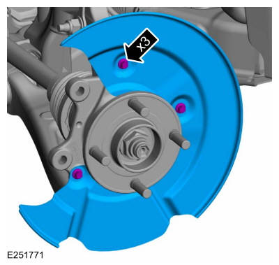
Removal and Installation - Brake Disc Shield
Removal
NOTE: Removal steps in this procedure may contain installation details.
Remove the brake disc.Refer to: Brake Disc (206-03 Front Disc Brake, Removal and Installation).
Remove the bolts and brake disc.
Torque: 80 lb.in (9 Nm)