Ford Ecosport: Automatic Transmission - 6-Speed Automatic Transmission – 6F35 / Description and Operation - Planetary Assembly
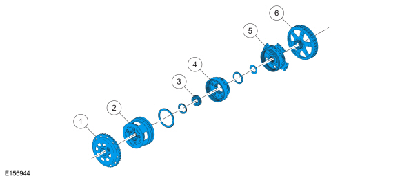
Planetary Gearset Exploded View

| Item | Description |
| 1 | Front planetary sun gear and shell assembly |
| 2 | Front planetary carrier/rear planetary ring gear assembly |
| 3 | Gear - center planetary sun |
| 4 | Center planetary carrier/front ring gear assembly |
| 5 | Rear planetary carrier/center ring gear assembly |
| 6 | Rear planetary sun gear and shell assembly |
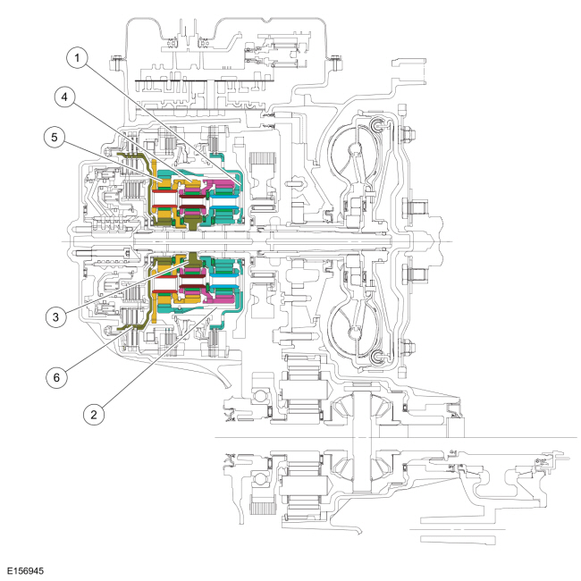
Planetary Gearset Cutaway View

Planetary Gearset
This transmission has 3 planetary gearsets to provide operation in reverse and 6 forward speeds.
The gearsets are comprised of the following components:
- Front planetary sun gear (part of the front sun gear and shell assembly)
- Front planetary carrier
- Front planetary ring gear
- Center planetary sun gear
- Center planetary carrier
- Center planetary ring gear
- Rear planetary ring gear
- Rear planetary carrier
- Rear planetary sun gear and shell assembly
The front planetary sun gear is splined to the forward (1, 2, 3, 4) clutch and is held stationary in 1st, 2nd, 3rd and 4th gears.
The front planetary carrier is splined to the rear planetary ring gear and transfers power from the rear planetary gearset to the front planetary gearset in 2nd, 3rd, 5th and 6th gears and reverse. The front planetary carrier is splined to the drive chain drive sprocket. The front planetary carrier is the output component for the planetary gearset.
The front planetary ring gear is splined to the center planetary carrier and transfers power from the center planetary gearset to the front planetary gearset in 1st, 2nd, 3rd and 4th gears.
The center planetary sun gear is splined to the input shaft and is used as input to the planetary gearsets in 1st, 2nd, 3rd and 4th gear.
The center planetary ring gear is splined to the rear planetary carrier and transfers power from the center planetary gearset to the rear planetary gearset in 3rd gear, from the rear planetary gearset to the center planetary gearset in 4th gear and is held stationary by the low One-Way Clutch (OWC) and low/reverse clutch in 1st gear and reverse.
The rear planetary carrier is splined to the overdrive (4, 5, 6) clutch hub and transfers power from the input shaft to the rear planetary carrier in 4th, 5th and 6th gears.
The rear planetary sun gear and shell assembly is splined to both the intermediate (2, 6) clutch and the direct (3, 5, R) clutch. The rear planetary sun gear and shell assembly is held stationary by the intermediate (2, 6) clutch in 2nd and 6th gear and is driven by the direct (3, 5, R) clutch in 3rd and 5th gears and reverse.
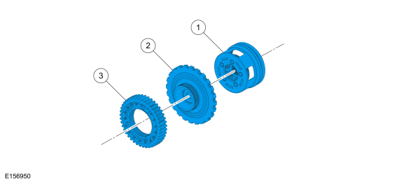
Front Planetary Carrier Hub Exploded View

| Item | Description |
| 1 | Front planetary carrier |
| 2 | Front planetary carrier hub/park gear |
| 3 | Drive chain drive sprocket |
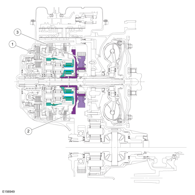
Front Planetary Carrier Hub Cutaway View

Front Planetary Carrier Hub (Output Hub)
The front planetary carrier hub/park gear is splined to the front planetary carrier and the drive chain drive sprocket. This allows torque to be transferred from the planetary gearset to the final drive gearset.
 Description and Operation - Final Drive
Final Drive Component Exploded View
Item
Description
1
Drive chain drive sprocket
2
Drive chain
3
Drive chain driven sprocket
4
Final drive planetary sun gear
5
Differential assembly
6
Final drive planet..
Other information:
Ford Ecosport 2014-2025 Service and Repair Manual: Removal and Installation - Passenger Door Window Control Switch
Special Tool(s) / General Equipment Interior Trim Remover Removal NOTE: Left hand drive (LHD) shown, right hand drive (RHD) similar. NOTE: Removal steps in this procedure may contain installation details. Release the clips and the tabs and remove the armrest side trim panel. Use the General Equipment: Interior Trim Remover ..
Ford Ecosport 2014-2025 Service and Repair Manual: Removal and Installation - Rear Seatbelt Retractor
Removal NOTE: Removal steps in this procedure may contain installation details. NOTE: LH shown, RH similar. Position the rear seat cushion to the full forward position. Position the carpet aside to access the seatbelt anchor. Remove the bolt and position the seatbel..

