Ford Ecosport: Supplemental Restraint System / Removal and Installation - Seatbelt Minder Sensor
Special Tool(s) /
General Equipment
Removal
NOTE:
Removal steps in this procedure may contain installation details.
NOTE:
LHD passenger seat shown, RHD passenger seat similar.
-
 WARNING:
Before beginning any service procedure in this
manual, refer to health and safety warnings in section 100-00 General
Information. Failure to follow this instruction may result in serious
personal injury.
Refer to: Pyrotechnic Device Health and Safety Precautions (100-00 General Information, Description and Operation).
-
Remove the front passenger seat.
Refer to: Front Seat (501-10A Front Seats, Removal and Installation).
-
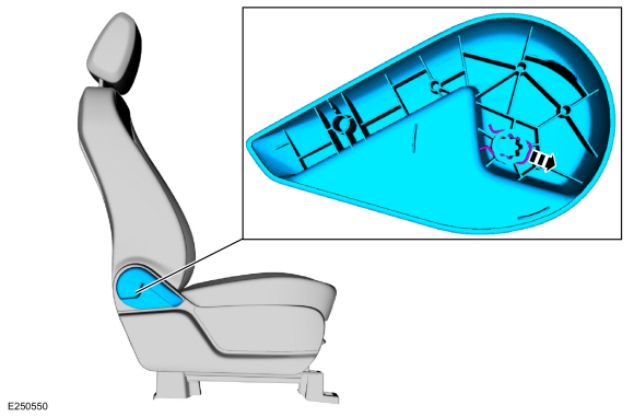
Remove the clip and the recline handle.
-
-
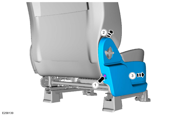
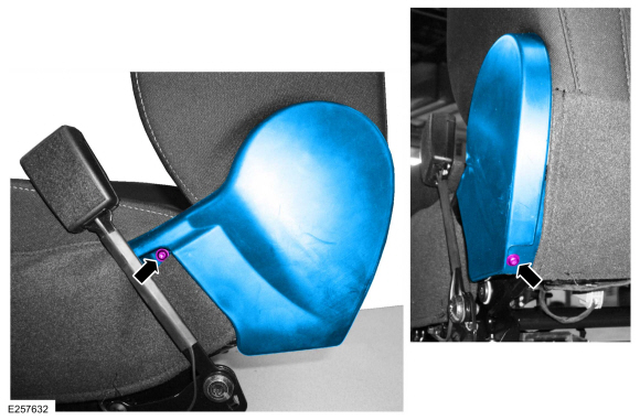
Remove the screw.
-
Lift the rear of the side shield up and out.
-
Slide forward and remove the side shield.
-
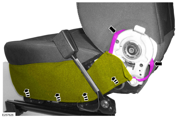
Remove the screws and the recliner cover.
-
Detach the strap and position the cushion cover apron upward.
-
-
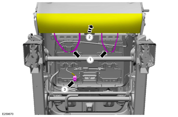
Detach the backrest cover straps.
-
Position the backrest cover upward.
-
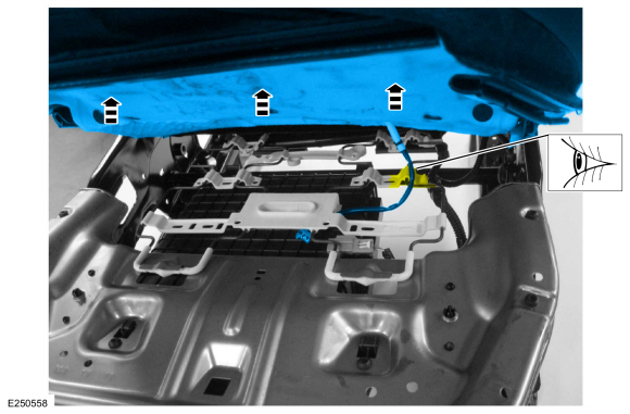
Disconnect the seatbelt minder sensor electrical connector.
-
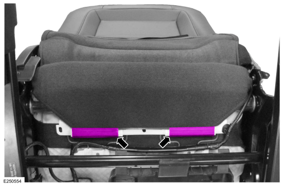
Detach the cushion cover rear J-clips.
-
-
On both sides.
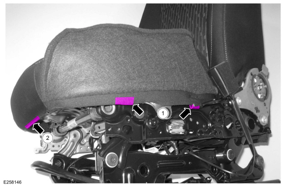
Detach the cushion cover J-clips.
-
Detach the cushion cover J-clip.
-
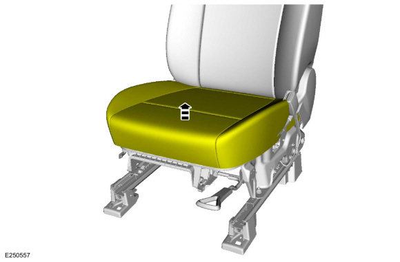
Lift up on the front seat cushion cover and foam assembly.
-
NOTE:
For correct installation, note the location of the
seatbelt minder sensor wiring pigtail as it passes through the seat
track.
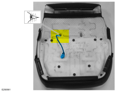
Route out the seatbelt minder sensor wiring pigtail and
remove the front seat cushion cover and foam as an assembly.
-
NOTE:
Follow the unique instructions or graphic for this step in the installation.
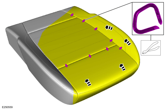
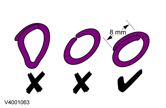
Remove the hog rings and position the cushion cover aside.
-
NOTE:
Follow the unique instructions or graphic for this step in the installation.
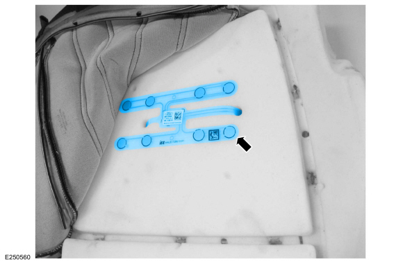
Remove the seatbelt minder sensor.
Installation
-
To install, reverse the removal procedure.
-
Route the seatbelt minder sensor wiring pigtail through the correct cushion foam hole.
-
Use the General Equipment: Hog Ring Plier
Removal
NOTE:
LH power seat shown, other seats similar.
NOTE:
Removal steps in this procedure may contain installation details.
Disconnect the electrical connector...
Removal
WARNING:
The following procedure prescribes critical repair steps
required for correct restraint system operation during a crash...
Other information:
B0052:11, B0052:12, B0052:13, B0052:1D
Refer to Wiring Diagrams Cell 46 for schematic and connector information.
Normal Operation and Fault Conditions
The RCM continuously monitors the passenger seatbelt buckle sensor circuits for the following faults:
Open circuit
Short to voltage
Short to ground
Current out of range
Faulted passenger..
Removal
NOTE:
Removal steps in this procedure may contain installation details.
Remove the ACM .
Disconnect and remove the center register air discharge temperature sensor.
Installation
To install, reverse the removal procedure.
..
 WARNING:
Before beginning any service procedure in this
manual, refer to health and safety warnings in section 100-00 General
Information. Failure to follow this instruction may result in serious
personal injury.
 Removal and Installation - Seat Position Sensor
 Removal and Installation - Second Row Seat Side Airbag
