Ford Ecosport: Rear End Sheet Metal Repairs / Removal and Installation - Rear Side Member Section
Ford Ecosport 2014-2025 Service and Repair Manual / Body and Paint / Rear End Sheet Metal Repairs / Removal and Installation - Rear Side Member Section
Special Tool(s) / General Equipment
| Resistance Spotwelding Equipment | |
| Spherical Cutter | |
| Grinder | |
| Air Body Saw | |
| MIG/MAG Welding Equipment | |
| Spot Weld Drill Bit | |
| Locking Pliers |
Materials
| Name | Specification |
|---|---|
| Seam Sealer TA-2-B, 3M™ 08308, LORD Fusor® 803DTM |
- |
Removal
NOTICE: The rear side member reinforcement is made of Dual-Phase (DP) 600 class steel and may be sectioned provided sectioning is done 50 mm or more from crush points/convolutes and suspension/drivetrain mounting locations.
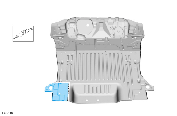
NOTE: The following procedure details sectioning of the rear portion of the rear side member where collision damage is minimal.
NOTE: LH side shown, RH side similar.
-
Restore the vehicle to pre-accident dimensions as required.
Refer to: Body and Frame (501-26 Body Repairs - Vehicle Specific Information and Tolerance Checks, Description and Operation).
-
Remove the following items:
-
Remove the back panel and reinforcement.
Refer to: Back Panel and Reinforcement (501-30 Rear End Sheet Metal Repairs, Removal and Installation).
-
Remove the back panel and reinforcement.
-
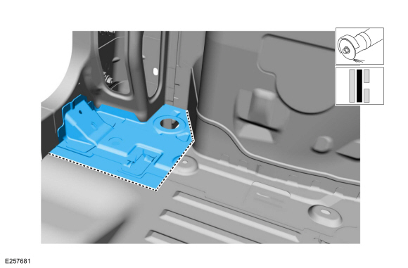
Remove the floor pan spot welds on the affected side.
Use the General Equipment: Spot Weld Drill Bit
 |
-
Carefully cut and remove section of the floor pan.
Use the General Equipment: Spherical Cutter
 |
-
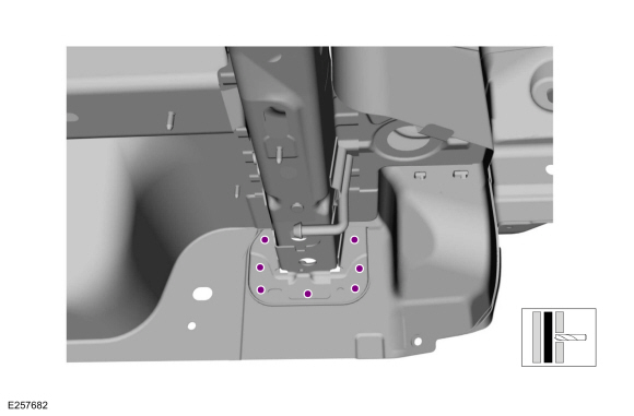
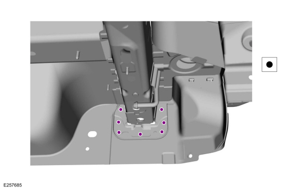
Remove spot welds on the frame rail flange.
Use the General Equipment: Spot Weld Drill Bit
 |
-
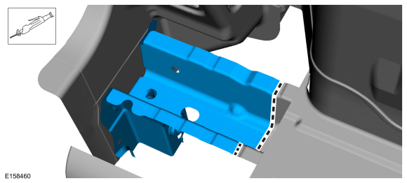
Carefully cut and remove the frame rail section.
Use the General Equipment: Air Body Saw
 |
Installation
NOTICE: The rear side member reinforcement is made of Dual-Phase (DP) 600 class steel and may be sectioned providing sectioning is done 50 mm or more from crush points/convolutes and suspension/drivetrain mounting locations.
-
Refer to: Joining Techniques (501-25 Body Repairs - General Information, General Procedures).
-
Dress all weld nuggets and rough edges.
Use the General Equipment: Grinder
-
Carefully measure and cut the service part to fit repair.
Use the General Equipment: Air Body Saw
 |
-
Cut to fit a section of floor panel from service replacement part.
Use the General Equipment: Air Body Saw
 |
-
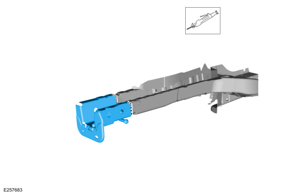
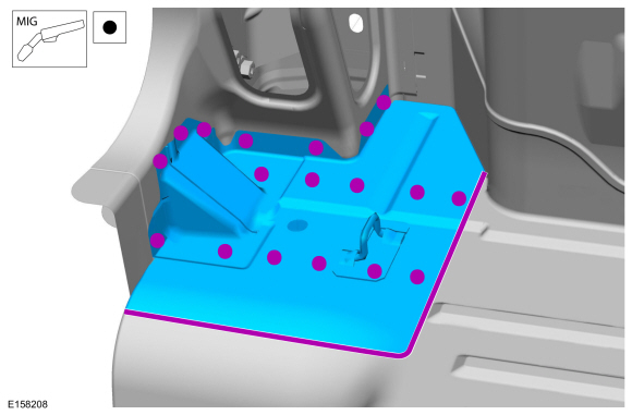
Install, properly position, clamp and seam weld the side member section.
Use the General Equipment: MIG/MAG Welding Equipment
Use the General Equipment: Locking Pliers
 |
-
Verify correct vehicle dimensions before final welding
Refer to: Body and Frame (501-26 Body Repairs - Vehicle Specific Information and Tolerance Checks, Description and Operation).
-
Spot weld the frame rail flange.
Use the General Equipment: Resistance Spotwelding Equipment
 |
-
Install the floor panel section and weld.
Use the General Equipment: Resistance Spotwelding Equipment
Use the General Equipment: MIG/MAG Welding Equipment
 |
-
Metal finish the repair area as required using typical metal finishing techniques.
-
Sealing work: All areas must be sealed to production level.
Material: Seam Sealer / TA-2-B, 3M™ 08308, LORD Fusor® 803DTM
-
Refinish the repair area using a Ford approved paint system.
-
Restore corrosion protection.
Refer to: Corrosion Prevention (501-25 Body Repairs - General Information, General Procedures).
-
Install the following items:
-
Install the back panel and reinforcement.
Refer to: Back Panel and Reinforcement (501-30 Rear End Sheet Metal Repairs, Removal and Installation).
-
Install the back panel and reinforcement.

 Removal and Installation - Back Panel
Special Tool(s) /
General Equipment
Resistance Spotwelding Equipment
8 mm Drill Bit
MIG/MAG Welding Equipment
Spot Weld Drill Bit
Locking Pliers
Materials
Name
Specification
Seam SealerTA-2-B, 3M™ 08308, LORD Fusor® 803DTM
-
Removal
NOTE:
The back panel is constructed of mild steel and
High-Strength low ..
Other information:
Ford Ecosport 2014-2025 Service and Repair Manual: Removal and Installation - Brake Disc Shield
Removal NOTE: Removal steps in this procedure may contain installation details. Remove the brake disc. Refer to: Brake Disc (206-03 Front Disc Brake, Removal and Installation). Remove the bolts and brake disc. Torque: 80 lb.in (9 Nm) Installation To install, reverse the removal procedure. ..
Ford Ecosport 2014-2025 Service and Repair Manual: General Procedures - Plastic Repairs
Special Tool(s) / General Equipment ALCV-200 Materials Name Specification Plastic Bonding AdhesiveTA-9 - Inspection NOTE: Plastics Identification WARNING: Before beginning any service procedure in this section, REFER to Safety Warnings in section 100-00 General Information. Failure to follow this instruction..
Categories
- Manuals Home
- 2nd Gen Ford Ecosport Service Manual (2014 - 2025)
- Engine
- Climate Control System - General Information
- Removal and Installation - Rear Bumper
- Diagnosis and Testing - Body Control Module (BCM)
- General Procedures - Transmission Fluid Level Check
Disassembly - Engine
Special Tool(s) / General Equipment
 205-153
(T80T-4000-W)
205-153
(T80T-4000-W)
Handle
 303-103
(T74P-6375-A)
303-103
(T74P-6375-A)
Holding Tool, Flywheel
T74P-77000-A
TKIT-2009TC-F
 303-1247
VCT Spark Plug Tube Seal Remover and Installer
TKIT-2006UF-FLM
TKIT-2006UF-ROW
 303-15
Copyright © 2025 www.foecosport2.com