Ford Ecosport: Fuel Tank and Lines - 2.0L Duratec-HE (129kW/175PS) / Removal and Installation - Fuel Tank Filler Pipe
Ford Ecosport 2014-2025 Service and Repair Manual / Fuel System / Fuel Tank and Lines - 2.0L Duratec-HE (129kW/175PS) / Removal and Installation - Fuel Tank Filler Pipe
Removal
-
Refer to: Gasoline and Gasoline-Ethanol Fuel Systems Health and Safety Precautions (100-00)
.
-
With the vehicle in NEUTRAL, position it on a hoist.
Refer to: Jacking and Lifting - Overview (100-02 Jacking and Lifting, Description and Operation).
-
Disconnect the battery ground cable.
Refer to: Battery Disconnect and Connect (414-01) .
-
NOTE: If the fuel tank is completely full, this step will lower the fuel level to the fuel tank inlet.
NOTE: The supplemental refueling adapter is located in the luggage compartment.
-
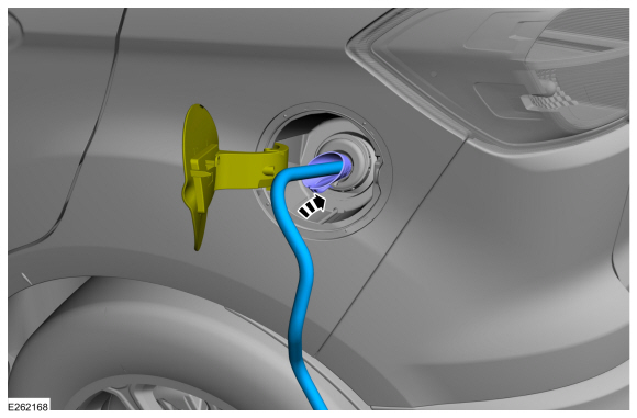
Install the supplemental refueling adapter and a
length of semi-rigid fuel drain tube into the Easy Fuel (capless) fuel
tank filler pipe.
-
Attach the Fuel Storage Tanker to the fuel drain
tube and drain as much fuel as possible from the Easy Fuel (capless)
fuel tank filler pipe, lowering the fuel level below the fuel tank inlet
spout.
-
Install the supplemental refueling adapter and a
length of semi-rigid fuel drain tube into the Easy Fuel (capless) fuel
tank filler pipe.
 |
-
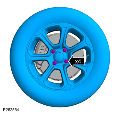
Remove the bolts and the rear LH wheel.
Torque: 98 lb.ft (133 Nm)
 |
-
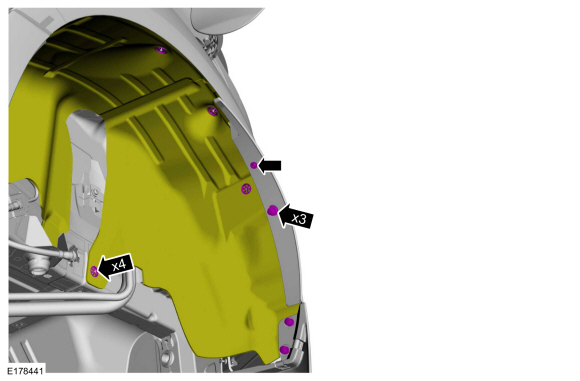
NOTE: Take extra care when handling the component.
Remove the retainers and position aside the LH rear wheel splash shield.
 |
-
-
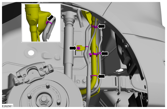
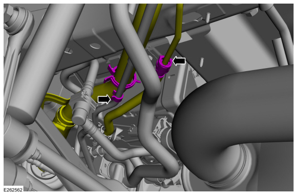
Disconnect the routing retainers.
-
Remove the fuel filler pipe mounting bracket bolt.
Torque: 97 lb.in (11 Nm)
-
Disconnect the routing retainers.
 |
-
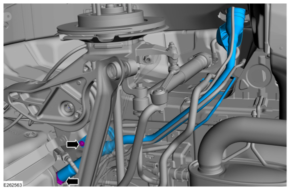
-
Disconnect the quick release coupling.
Refer to: Quick Release Coupling (310-00I) .
-
Disconnect the routing retainer.
-
Disconnect the quick release coupling.
 |
-
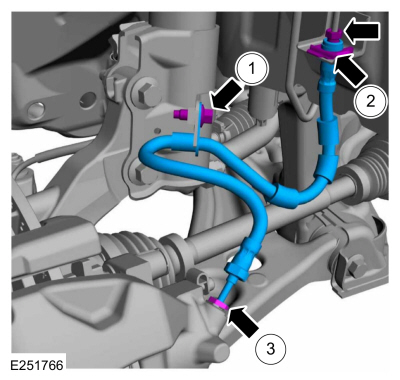
-
Loosen the hose clamp and disconnect the hose.
Torque: 35 lb.in (4 Nm)
-
Remove the mounting bracket bolt and the fuel tank filler pipe.
Torque: 97 lb.in (11 Nm)
-
Loosen the hose clamp and disconnect the hose.
 |
Installation
-
To install, reverse the removal procedure.
 Removal and Installation - Fuel Tank
Special Tool(s) /
General Equipment
Transmission Jack
Retaining Strap
Removal
NOTE:
Removal steps in this procedure may contain installation details...

Other information:
Ford Ecosport 2014-2025 Service and Repair Manual: Removal and Installation - Selector Shaft Seal
Special Tool(s) / General Equipment 307-581Manual lever seal installerTKIT-2006UF-FLMTKIT-2006UF-ROW Flat Headed Screw Driver Removal Remove the TR sensor. Refer to: Transmission Range (TR) Sensor (307-01B Automatic Transmission - 6-Speed Automatic Transmission – 6F35, Removal and Installation). Remove and discard the ..
Ford Ecosport 2014-2025 Service and Repair Manual: Removal and Installation - Air Conditioning (A/C) Pressure Transducer
Removal NOTE: Removal steps in this procedure may contain installation details. Remove the A/C pressure transducer. Disconnect the electrical connector. Remove the A/C pressure transducer. Torque: 71 lb.in (8 Nm) Installation To install, reverse the removal procedure. ..
Categories
- Manuals Home
- 2nd Gen Ford Ecosport Service Manual (2014 - 2025)
- Body and Paint
- Diagnosis and Testing - Powertrain Control Module (PCM) Input and Output Controls
- General Procedures - Transmission Fluid Level Check
- General Procedures - Battery Charging
- Removal and Installation - Front Seat
Removal and Installation - Front Brake Flexible Hose
Removal
Remove the wheel and tire.Refer to: Wheel and Tire (204-04A Wheels and Tires, Removal and Installation).
Remove the brake flexible hose bracket bolt.
Disconnect the brake tube fitting and remove the brake hose clip.
Loosen the brake hose fitting and remove the brake flexible hose.
Copyright © 2025 www.foecosport2.com