Ford Ecosport: Uni-Body, Subframe and Mounting System / Removal and Installation - Front Subframe
Special Tool(s) /
General Equipment
| Tie Rod End Remover |
| Transmission Jack |
Removal
All vehicles
NOTICE:
Suspension fasteners are critical parts that affect the
performance of vital components and systems. Failure of these fasteners
may result in major service expense. Use the same or equivalent parts if
replacement is necessary. Do not use a replacement part of lesser
quality or substitute design. Tighten fasteners as specified.
-
NOTICE:
Disconnect the battery ground cable anytime the
steering gear is being serviced or damage to the steering gear internal
power relay may occur resulting in steering gear replacement.
Disconnect the battery ground cable.
Refer to: Battery Disconnect and Connect (414-01 Battery, Mounting and Cables, General Procedures).
-
With the vehicle in NEUTRAL, position it on a hoist.
Refer to: Jacking and Lifting - Overview (100-02 Jacking and Lifting, Description and Operation).
-
NOTICE:
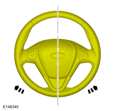
Make sure that the steering wheel lock is engaged.
Steering wheel in straight ahead position.
-
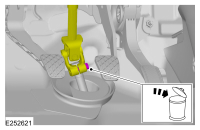
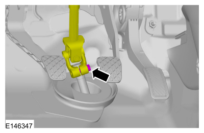
 WARNING:
Do not reuse steering column shaft bolts. This
may result in fastener failure and steering column shaft detachment or
loss of steering control. Failure to follow this instruction may result
in serious injury to vehicle occupant(s).
WARNING:
Do not reuse steering column shaft bolts. This
may result in fastener failure and steering column shaft detachment or
loss of steering control. Failure to follow this instruction may result
in serious injury to vehicle occupant(s).
Remove and discard the steering column shaft coupler bolt and separate the coupler from the steering shaft.
-
Remove the wheels and tires.
Refer to: Wheel and Tire (204-04A Wheels and Tires, Removal and Installation).
-
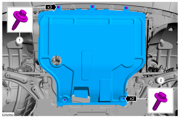
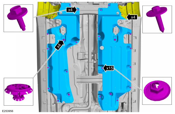
Remove the retainers and the under body shield.
-
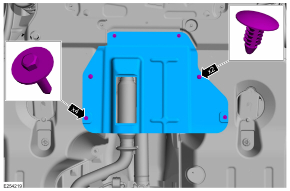
Remove the retainers and the under body air deflector shield.
-
Remove the retainers and the underbody side panels.
-
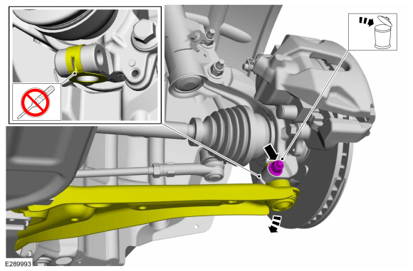
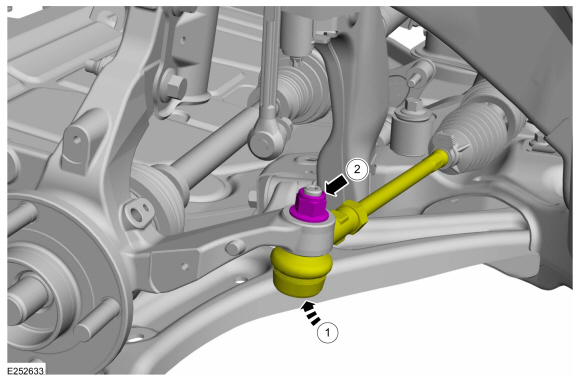
NOTICE:
Do not use a prying device or separator fork
between the ball joint and the wheel knuckle. Damage to the ball joint
or ball joint seal may result. Only use the pry bar by inserting it into
the lower arm body opening.
NOTICE:
Use care when releasing the lower arm and wheel
knuckle into the resting position or damage to the ball joint seal may
occur.
On both sides.
Remove and discard the ball joint pinch bolt and nut and separate the ball joint from the wheel knuckle.
-
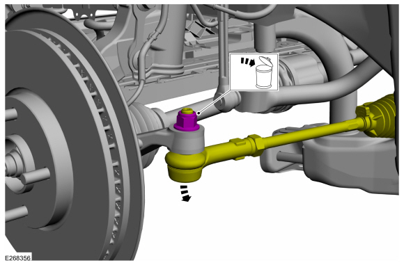
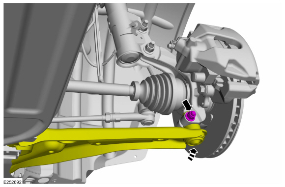
NOTICE:
Do not use a hammer to separate the outer
tie-rod end from the wheel knuckle or damage to the wheel knuckle may
result.
NOTICE:
Use care when installing the tie rod separator or damage to the outer tie-rod end boot may occur.
On both sides.
Remove and discard the tie rod end nut and separate the tie rod end from the wheel knuckle.
Use the General Equipment: Tie Rod End Remover
-
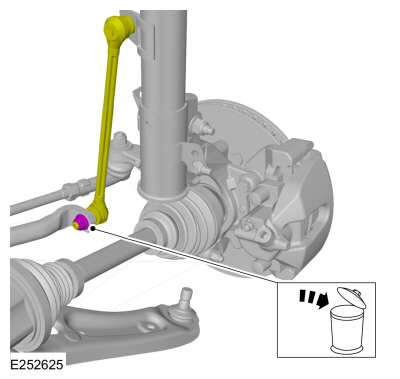
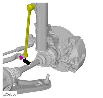
NOTE:
The stabilizer bar links are designed with low friction ball joints that have a low breakaway torque.
NOTE:
Use the hex-holding feature to prevent the ball
stud from turning while removing or installing the stabilizer bar link
nut.
On both sides.
Remove and discard the stabilizer bar link lower nut and position aside the stabilizer bar link.
-
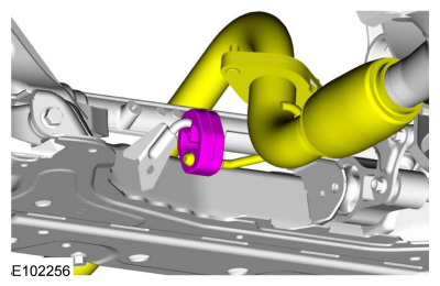
Remove the bolt and position the engine roll restrictor aside.
Vehicles with 1.0L EcoBoost, 1.5L Duratorq-TDCi
-
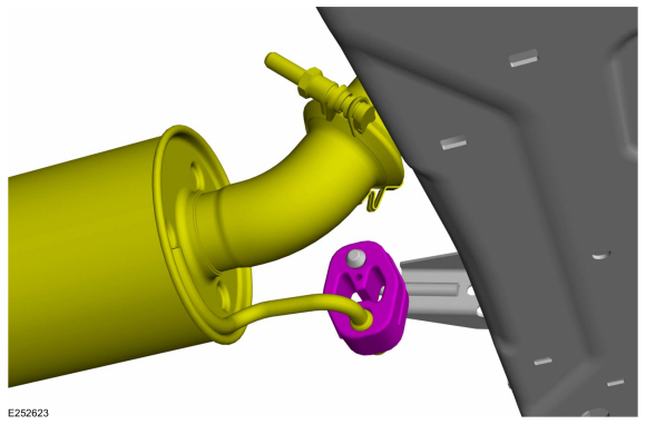
Detach the exhaust hanger isolator.
1.5L
-
Detach the exhaust hanger isolator.
All vehicles
-
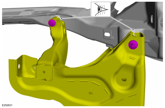
NOTE:
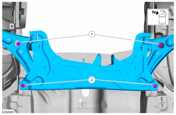
Index-mark the subframe for reference during installation.
On both sides.
Mark the position of front subframe.
-
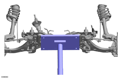
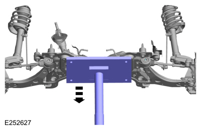
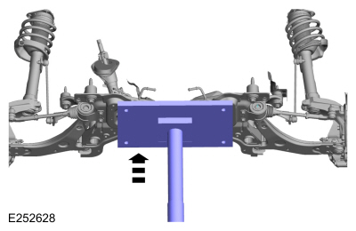
Position a transmission jack under the front subframe.
Use the General Equipment: Transmission Jack
-
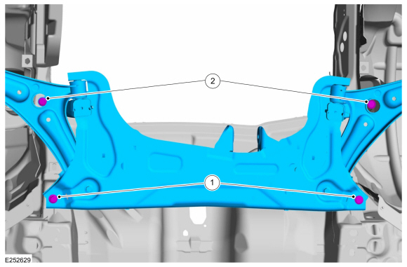
-
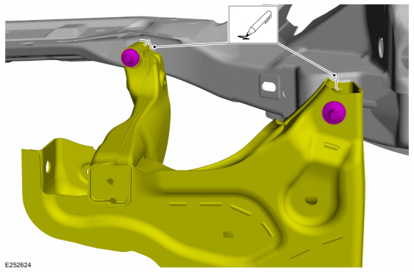
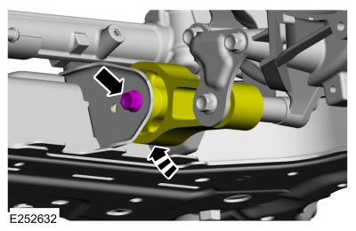
Remove and discard the forward front subframe bolts.
-
Remove and discard the rearward front subframe bolts.
-
Lower the subframe.
Use the General Equipment: Transmission Jack
-
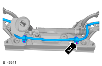
Remove the stabilizer bar bracket bolts and the stabilizer bar.
-
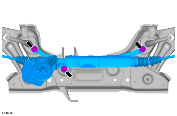
Remove the steering gear mounting bolts and the steering gear.
-
Remove the lower arm.
-
Remove the lower arm forward bolt.
-
Remove the lower arm rearward bolt.
Installation
All vehicles
-
WARNING:
Make sure that new bolts are installed.
NOTE:
This step is only necessary when installing a new component.
Install the lower arm.
-
Install the lower arm forward bolt.
Torque:
Stage 1:
76 lb.ft (103 Nm)
Stage 2:
180°
-
Install the lower arm rearward bolt.
Torque:
Stage 1:
46 lb.ft (63 Nm)
Stage 2:
180°
-
Install the steering gear and steering gear mounting bolts.
Torque:
66 lb.ft (90 Nm)
-
Install the stabilizer bar and the stabilizer bar bracket bolts.
Torque:
35 lb.ft (48 Nm)
-
Partially raise the subframe and position it to the vehicle.
Use the General Equipment: Transmission Jack
-
NOTE:
Do not tighten the bolts at this stage.
-
Install the new rearward front subframe bolts.
-
Install the new forward front subframe bolts.
-
On both sides.
Position the stabilizer bar links and install the new stabilizer bar link lower nut.
Torque:
46 lb.ft (63 Nm)
-
NOTE:
If installing the subframe that was previously removed.
On both sides.
Align the index marks made during removal.
-
-
Tighten the new rearward front subframe bolts.
Torque:
Stage 1:
74 lb.ft (100 Nm)
Stage 2:
240°
-
Tighten the new forward front subframe bolts.
Torque:
Stage 1:
46 lb.ft (63 Nm)
Stage 2:
60°
1.5L
-
Attach the exhaust hanger isolator.
Vehicles with 1.0L EcoBoost, 1.5L Duratorq-TDCi
-
Attach the exhaust hanger isolator.
All vehicles
-
Position the engine roll restrictor and install the engine roll restrictor bolt.
Torque:
59 lb.ft (80 Nm)
-
-
Attach the tie rod to the wheel knuckle.
-
Install the new tie rod nut.
Torque:
39 lb.ft (53 Nm)
-
On both sides.
Connect the lower ball joint to the wheel knuckle and install the new ball joint pinch bolt and nut.
Torque:
38 lb.ft (52 Nm)
-
Install the underbody side panels and the retainers.
Torque:
13 lb.in (1.5 Nm)
-
Install the under body air deflector shield and and the retainers.
-
Install the under body shield and the retainers.
Torque:
1:
13 lb.in (1.5 Nm)
2:
22 lb.in (2.5 Nm)
-
Install the wheels and tires.
Refer to: Wheel and Tire (204-04A Wheels and Tires, Removal and Installation).
-
WARNING:
Do not reuse steering column shaft bolts. This
may result in fastener failure and steering column shaft detachment or
loss of steering control. Failure to follow this instruction may result
in serious injury to vehicle occupant(s).
Position the steering shaft coupler and install the new steering shaft coupler bolt.
Torque:
25 lb.ft (34 Nm)
-
Connect the battery ground cable.
Refer to: Battery Disconnect and Connect (414-01 Battery, Mounting and Cables, General Procedures).
-
Check and if necessary adjust front toe.
Refer to: Front Toe Adjustment (204-00 Suspension System - General Information, General Procedures).
Overview
The front subframe is bolted to the body and is used to:
aid in structural support.
provide mounting surfaces for the steering gear...
Special Tool(s) /
General Equipment
Flat Headed Screw Driver
Transmission Jack
Removal
NOTICE:
Suspension fasteners are critical parts that affect the
performance of vital components and systems...
Other information:
Removal
NOTE:
Removal steps in this procedure may contain installation details.
All vehicles
Detach the parking brake control boot and position the boot upward on the handle.
Remove and discard the lock nut...
Special Tool(s) /
General Equipment
Flat-Bladed Screwdriver
Removal
NOTICE:
Suspension fasteners are critical parts that affect the
performance of vital components and systems. Failure of these fasteners
may result in major service expense...


 Description and Operation - Frame Assembly - Overview
 Removal and Installation - Rear Subframe - AWD
 WARNING:
Wear eye and ear protection when servicing a vehicle.
Failure to follow this instruction may result in serious personal
injury.
WARNING:
Wear eye and ear protection when servicing a vehicle.
Failure to follow this instruction may result in serious personal
injury.