Ford Ecosport: Supplemental Restraint System / Removal and Installation - Driver Knee Airbag
Special Tool(s) / General Equipment
| Pick Hook | |
| Interior Trim Remover |
Removal
 WARNING:
The following procedure prescribes critical repair steps
required for correct restraint system operation during a crash. Follow
all notes and steps carefully. Failure to follow step instructions may
result in incorrect operation of the restraint system and increases the
risk of serious personal injury or death in a crash.
WARNING:
The following procedure prescribes critical repair steps
required for correct restraint system operation during a crash. Follow
all notes and steps carefully. Failure to follow step instructions may
result in incorrect operation of the restraint system and increases the
risk of serious personal injury or death in a crash.
NOTE: Removal steps in this procedure may contain installation details.
-
Refer to: Pyrotechnic Device Health and Safety Precautions (100-00 General Information, Description and Operation).
WARNING:
Before beginning any service procedure in this
manual, refer to health and safety warnings in section 100-00 General
Information. Failure to follow this instruction may result in serious
personal injury.
-
Depower the SRS .
Refer to: Supplemental Restraint System (SRS) Depowering (501-20B Supplemental Restraint System, General Procedures).
-
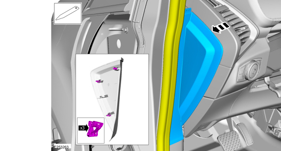
Position aside the weather strip, release the clips and remove the LH instrument panel side trim panel.
 |
-
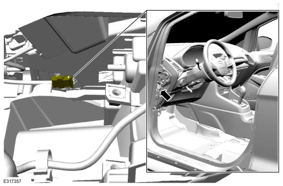
Locate the driver knee airbag electrical connector.
 |
-
-
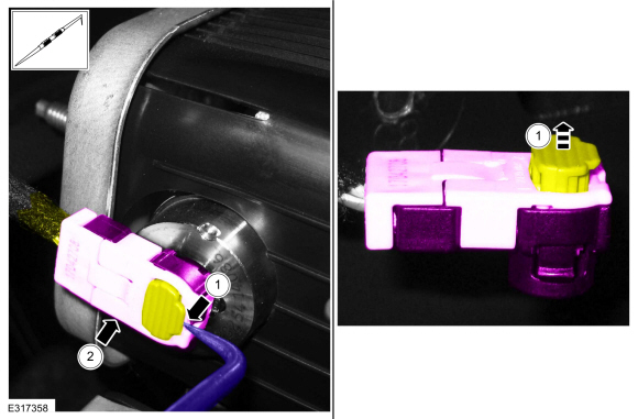
Lift and release the driver knee airbag electrical connector locking wedge.
Use the General Equipment: Pick Hook
-
Disconnect the driver knee airbag electrical connector.
-
Lift and release the driver knee airbag electrical connector locking wedge.
 |
-
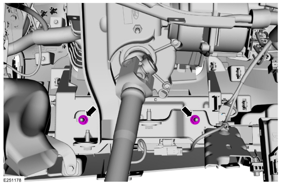
Remove the screws and the instrument panel insulator.
 |
-
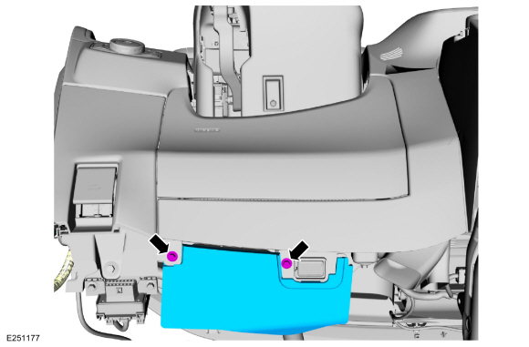
Remove the driver knee airbag nuts.
Torque: 71 lb.in (8 Nm)
 |
-
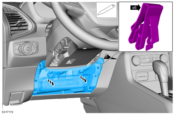
Detach the clips and remove the driver knee airbag.
Use the General Equipment: Interior Trim Remover
 |
Installation
WARNING:
Incorrect repair techniques or actions can cause an
accidental Supplemental Restraint System deployment. Make sure the
restraint system is depowered before reconnecting the component. Refer
to the Supplemental Restraint System depowering General Procedure in
section 501-20B. Failure to precisely follow depowering instructions
could result in serious personal injury from an accidental deployment.
-
To install, reverse the removal procedure.
-
Repower the SRS .
Refer to: Supplemental Restraint System (SRS) Repowering (501-20B Supplemental Restraint System, General Procedures).
 Removal and Installation - Driver Airbag
Special Tool(s) /
General Equipment
Flat-Bladed Screwdriver
Removal
WARNING:
The following procedure prescribes critical repair steps
required for correct restraint system operation during a crash...
 Removal and Installation - Front Door Side Impact Sensor - Vehicles With: Rear Seat Side Airbag
Removal
WARNING:
The following procedure prescribes critical repair steps
required for correct restraint system operation during a crash...
Other information:
Ford Ecosport 2014-2026 Service and Repair Manual: Description and Operation - Transmission Description
Disassembled Views Auto-Start-Stop Item Part Number Description 1 70057005 Transmission case 2 7A1307A130 Clutch support tower 3 7D0197D019 Clutch support tower seals (4 required) 4 W302855W302855 Clutch support tower bolt (3 required) 5 7F2427F242 No..
Ford Ecosport 2014-2026 Service and Repair Manual: Removal and Installation - Rocker Panel Inner Reinforcement
Special Tool(s) / General Equipment Resistance Spotwelding Equipment Grinder Belt Sander 8 mm Drill Bit MIG/MAG Welding Equipment Spot Weld Drill Bit Locking Pliers Removal NOTE: The rocker panel inner reinforcement is made of DP (Dual Phase) 800 steel and cannot be sectioned. It must be removed at factory seams. ..
Categories
- Manuals Home
- 2nd Gen Ford Ecosport Service Manual (2014 - 2026)
- Service Information
- General Procedures - Battery Charging
- Diagnosis and Testing - Evaporative Emissions
- Removal and Installation - Evaporative Emission Canister Purge Valve
- Removal and Installation - Starter Motor
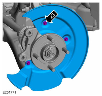
Removal and Installation - Brake Disc Shield
Removal
NOTE: Removal steps in this procedure may contain installation details.
Remove the brake disc.Refer to: Brake Disc (206-03 Front Disc Brake, Removal and Installation).
Remove the bolts and brake disc.
Torque: 80 lb.in (9 Nm)