Ford Ecosport: Hydraulic Brake Actuation / Removal and Installation - Brake Pedal and Bracket
Special Tool(s) /
General Equipment
Removal
NOTE:
Removal steps in this procedure may contain installation details.
NOTE:
LHD shown, RHD similar.
-
Remove the driver knee airbag.
Refer to: Driver Knee Airbag (501-20B Supplemental Restraint System, Removal and Installation).
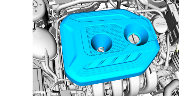
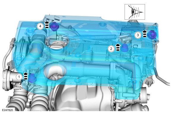
1.5L/2.0L
-
Remove the engine appearance cover.
1.5L
-
Remove the engine appearance cover.
All vehicles
-
Remove the cowl panel grille.
Refer to: Cowl Panel Grille (501-02 Front End Body Panels, Removal and Installation).
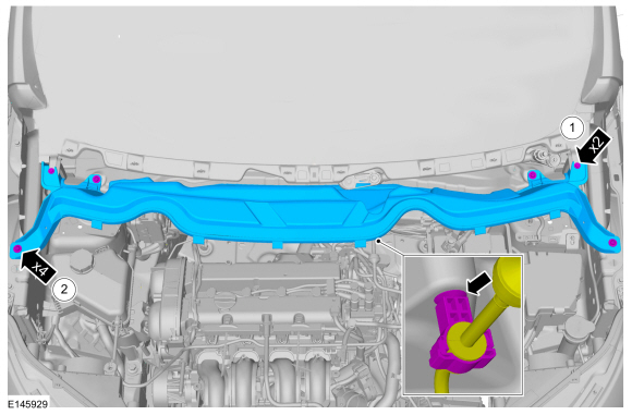
-
Remove the cowl panel bolts, position aside the windshield washer line and remove the cowl panel.
-
Remove the bolts.
Torque:
27 lb.in (3 Nm)
-
Remove the bolts.
Torque:
44 lb.in (5 Nm)
-
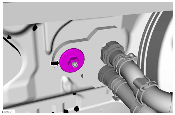
Remove the HVAC nut.
Torque:
9 lb.in (1 Nm)
-
Remove the cowl to in-vehicle cross beam bolt.
Torque:
22 lb.ft (30 Nm)
-
Remove the floor console.
Refer to: Floor Console (501-12 Instrument Panel and Console, Removal and Installation).
-
Remove the A-pillar trim panels.
Refer to: A-Pillar Trim Panel (501-05 Interior Trim and Ornamentation, Removal and Installation).
-
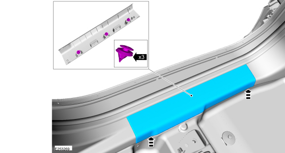
Release the retainers and remove the LH scuff plate.
-
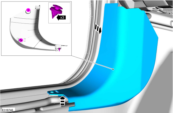
Release the retainers and remove the LH lower cowl trim panel.
-
Remove the hood release handle.
Refer to: Hood Latch Release Handle (501-14 Handles, Locks, Latches and Entry Systems, Removal and Installation).
-
Remove the driver side front door only.
Refer to: Front Door (501-03 Body Closures, Removal and Installation).
-
NOTE:
Driver side door opening, upper cowl.
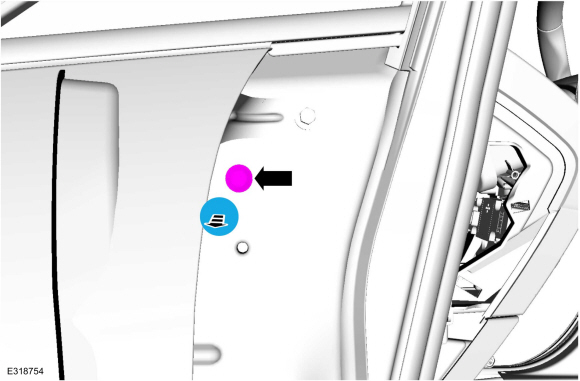
Remove the bolt cover and the LH upper cowl on in-vehicle cross beam bolt.
Torque:
18 lb.ft (25 Nm)
-
NOTE:
Do not allow the steering wheel to rotate while
the steering column shaft is disconnected or damage to the clockspring
may result.
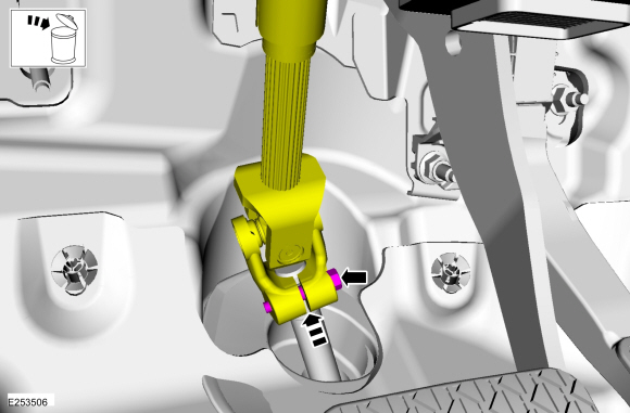
Secure the steering column.
-
 WARNING:
Do not reuse steering column shaft bolts. This
may result in fastener failure and steering column shaft detachment or
loss of steering control. Failure to follow this instruction may result
in serious injury to vehicle occupant(s).
NOTICE:
Remove and discard the lower steering column shaft
coupler bolt and separate the steering column shaft coupler from the
steering shaft.
Torque:
25 lb.ft (34 Nm)
-
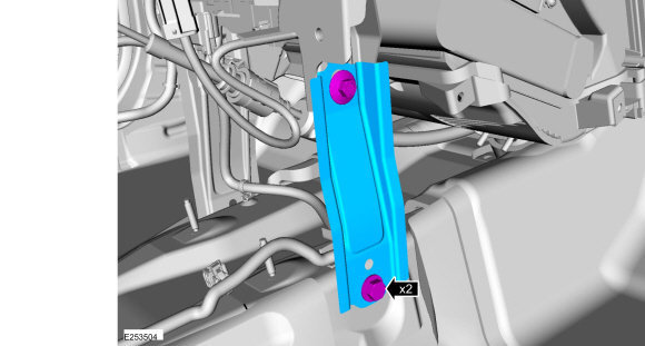
Remove the bolts and the RH side instrument panel center support brace.
Torque:
18 lb.ft (25 Nm)
-
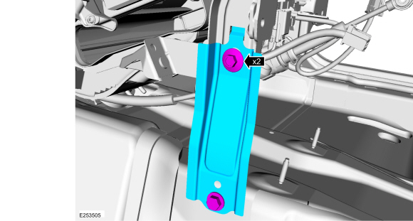
Remove the bolts and the LH side instrument panel center support brace.
Torque:
18 lb.ft (25 Nm)
-
Remove the battery tray.
Refer to: Battery Tray (414-01 Battery, Mounting and Cables, Removal and Installation).
-
-
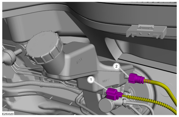
Disconnect the brake fluid level sensor electrical connector.
-
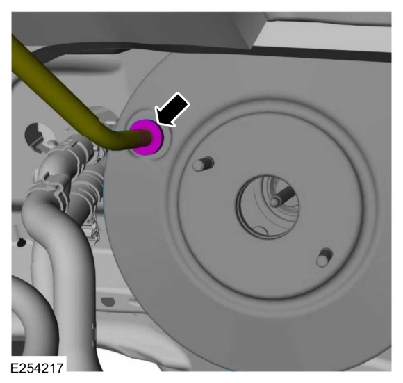
NOTICE:
Make sure that all openings are sealed.
If equipped.
Disconnect the clutch master cylinder tube.
-
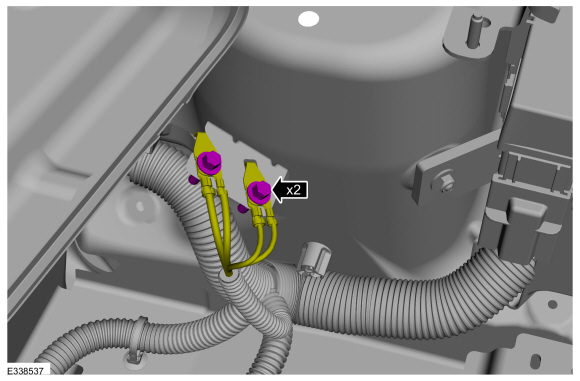
Remove the ground strap bolts.
Torque:
106 lb.in (12 Nm)
-
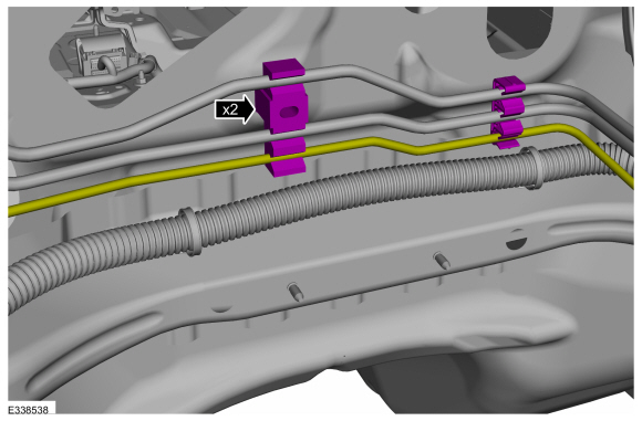
Position the brake line clip off of the bulkhead stud and release the lower brake line from the clips.
NOTICE:
Do not service the brake pedal or brake booster without
first removing the stoplamp switch. This switch must be removed with
the brake pedal in the at-rest position. The switch plunger must be
compressed for the switch to rotate in the bracket. Attempting to remove
the switch when the plunger is extended (during pedal apply) will
result in damage to the switch.
-
Remove the stoplamp switch.
Refer to: Stoplamp Switch (417-01 Exterior Lighting, Removal and Installation).
-
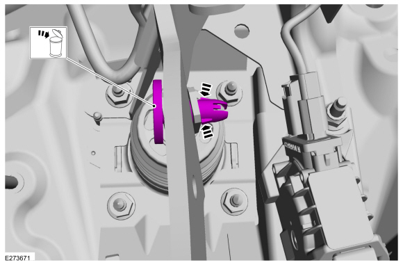
Detach the check valve from the brake booster.
-
Press the tabs and remove the clevis pin. Discard the pin.
-
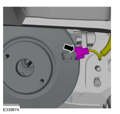
Disconnect the vacuum sensor electrical connector.
-
Remove the accelerator pedal.
Refer to: Accelerator Pedal (310-02 Acceleration Control, Removal and Installation).
-
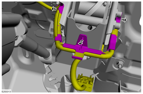
Detach the wiring harness retainers and position the wiring harness aside.
-
NOTE:
Removing the lower steering column shroud will provide access to the top brake pedal bracket nut.
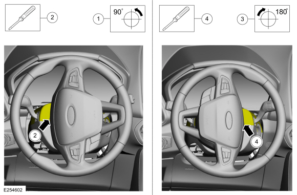
Release the upper steering column shroud front clips.
-
Rotate the steering wheel 90 degrees to the left.
-
Release the LH tab.
Use the General Equipment: Flat-Bladed Screwdriver
-
Rotate the steering wheel 180 degrees to the right.
-
Release the RH tab.
Use the General Equipment: Flat-Bladed Screwdriver
-
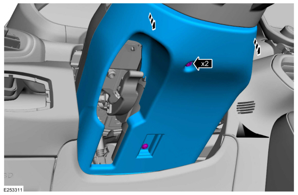
Remove the screws and the lower steering column shroud.
-
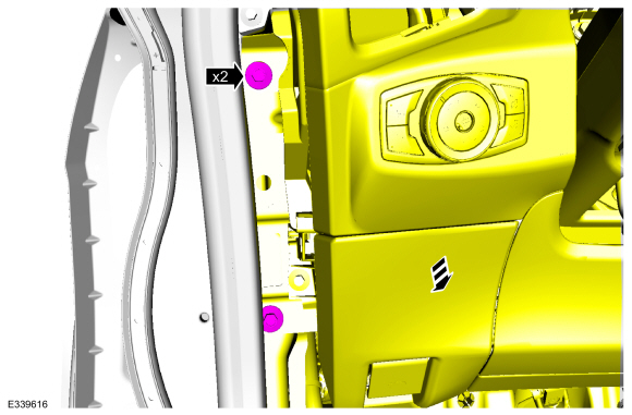
Remove the LH instrument panel bolts, and pull the left side of the instrument panel rearward to get access to the brake pedal.
Torque:
18 lb.ft (25 Nm)
-
NOTE:
This step requires the aid of another technician.
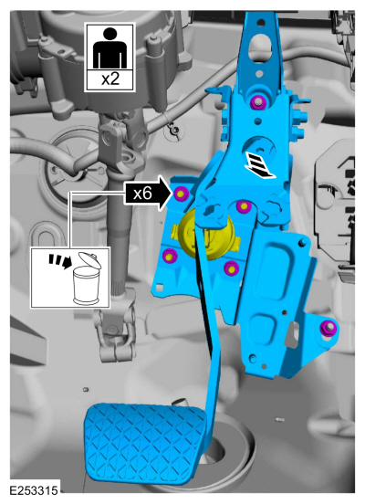
Remove the nuts, and pull the brake booster away from the cowl enough to remove the brake pedal and bracket.
Torque:
18 lb.ft (25 Nm)
Installation
-
NOTICE:
Do not press, pull or otherwise move the brake pedal
while installing the stoplamp switch. Install this switch with the
booster push rod attached to the brake pedal and with the brake pedal in
the at-rest position. Installing this switch with the pedal in any
other position results in incorrect adjustment and damages the switch.
To install, reverse the removal procedure.
-
NOTICE:
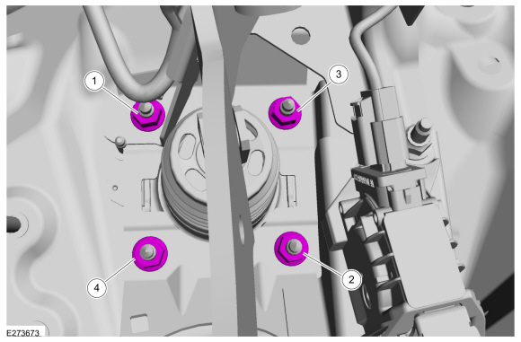
Make sure that the brake booster pushrod is correctly located.
Install the brake booster and tighten the nuts in sequence.
Torque:
18 lb.ft (25 Nm)
-
If equipped with manual transmission
. Bleed the clutch system.
Refer to: Clutch System Bleeding (308-02 Clutch Controls - 5-Speed Manual Transmission – B5/IB5, General Procedures).
Materials
Name
Specification
Motorcraft® DOT 4 LV High Performance Motor Vehicle Brake FluidPM-20
WSS-M6C65-A2
Removal
NOTE:
Removal steps in this procedure may contain installation details...
Other information:
Removal
WARNING:
The following procedure prescribes critical repair steps
required for correct restraint system operation during a crash. Follow
all notes and steps carefully. Failure to follow step instructions may
result in incorrect operation of the restraint system and increases the
risk of serious personal injury or death in a crash.
NOTE:
Removal steps in this..
Introduction
WARNING:
Always handle all solvents, sealers and adhesives with
extreme care. Some contain chemicals or give off fumes which can be
dangerous to health. Always follow the manufacturers instructions. If in
doubt about any substance, particularly a solvent, DO NOT use it.
NOTICE:
If in doubt about the suitability of any proprietary solvent
or sealer for..

 WARNING:
Do not reuse steering column shaft bolts. This
may result in fastener failure and steering column shaft detachment or
loss of steering control. Failure to follow this instruction may result
in serious injury to vehicle occupant(s).
 Removal and Installation - Brake Master Cylinder

