Ford Ecosport: Side Panel Sheet Metal Repairs / Removal and Installation - B-Pillar and Reinforcement
Special Tool(s) /
General Equipment
| Resistance Spotwelding Equipment |
| Spherical Cutter |
| Hot Air Gun |
| Air Body Saw |
| 8 mm Drill Bit |
| MIG/MAG Welding Equipment |
| Spot Weld Drill Bit |
| Locking Pliers |
Removal
NOTICE:
Protect the vehicle interior from damage during repair process.
NOTE:
Factory welds may be substituted with resistance or metal
inert gas (MIG) plug welds. Resistance welds may not be placed directly
over original location. They must be placed adjacent to original
location and match factory welds in quantity. Metal inert gas (MIG) plug
welds must equal factory welds in both location and quantity.
-
Depower the SRS .
Refer to: Supplemental Restraint System (SRS) Depowering (501-20B Supplemental Restraint System, General Procedures).
-
Remove the side curtain air bag.
Refer to: Side Curtain Airbag (501-20B Supplemental Restraint System, Removal and Installation).
-
Remove the B-pillar trim panel.
Refer to: B-Pillar Trim Panel (501-05 Interior Trim and Ornamentation, Removal and Installation).
-
Remove the seat belt height adjuster.
Refer to: Seatbelt Shoulder Height Adjuster (501-20A Seatbelt Systems, Removal and Installation).
-
Release the clips and remove the front door scuff plate trim panel.
-
Release the clips and remove the rear door scuff plate trim panel.
-
Dimensionally restore the vehicle to a pre-accident condition.
Refer to: Body and Frame (501-26 Body Repairs - Vehicle Specific Information and Tolerance Checks, Description and Operation).
-
-
Remove the front seat.
Refer to: Front Seat (501-10A Front Seats, Removal and Installation).
-
Remove the rear door
Refer to: Rear Door (501-03 Body Closures, Removal and Installation).
-
Reposition the carpeting and the wiring harness away from the working area.
-
Remove the front door striker and rear door hinges on the body.
-
-
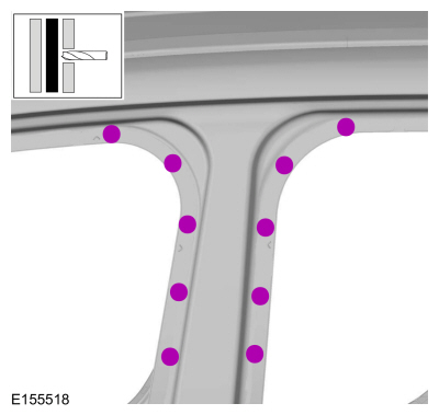
Measure and cut B-pillar service part and remove the welds.
Use the General Equipment: Air Body Saw
Use the General Equipment: Spot Weld Drill Bit
-
-
Break the adhesive bond and remove the B-pillar outer sheet metal.
Use the General Equipment: Hot Air Gun
-
-
Remove the welds.
Use the General Equipment: Spot Weld Drill Bit
-
-
Measure, cut and remove the outer sheet metal only.
Use the General Equipment: Air Body Saw
-
-
Remove the welds.
Use the General Equipment: Spot Weld Drill Bit
-
-
Remove the welds.
Use the General Equipment: Spot Weld Drill Bit
-
-
Remove the welds.
Use the General Equipment: Spot Weld Drill Bit
-
-
Remove the welds and the B pillar inner.
Use the General Equipment: Spot Weld Drill Bit
Installation
NOTICE:
Protect the vehicle interior from damage during repair process.
NOTE:
Factory welds may be substituted with resistance or metal
inert gas (MIG) plug welds. Resistance welds may not be placed directly
over original location. They must be placed adjacent to original
location and match factory welds in quantity. Metal inert gas (MIG) plug
welds must equal factory welds in both location and quantity.
-
Refer to: Plastic Repairs (501-25 Body Repairs - General Information, Description and Operation).
-
NOTE:
Sealer or adhesive must not be applied in welding
zones. Areas which were bonded or sealed needs to be thoroughly sealed
afterwards.
Refer to: Plastic Repairs (501-25 Body Repairs - General Information, Description and Operation).
-
Drill plug weld holes.
Use the General Equipment: 8 mm Drill Bit
-
Install plug welds.
Use the General Equipment: MIG/MAG Welding Equipment
-
Drill plug weld holes.
Use the General Equipment: 8 mm Drill Bit
-
-
-
Install, properly position, clamp and install resistance spot welds.
Use the General Equipment: Resistance Spotwelding Equipment
Use the General Equipment: Locking Pliers
-
-
Puddle weld 2 panel layer.
Use the General Equipment: MIG/MAG Welding Equipment
-
-
Install plug welds.
Use the General Equipment: MIG/MAG Welding Equipment
-
Carefully measure the replacement service parts and cut to fit repair area.
Use the General Equipment: Air Body Saw
Use the General Equipment: Spherical Cutter
-
Install service panel and clamp in position.
Refer to: Joining Techniques (501-25 Body Repairs - General Information, General Procedures).
Use the General Equipment: Locking Pliers
-
Install spot welds.
Use the General Equipment: Resistance Spotwelding Equipment
-
-
Seam weld sectioning joints using a MIG welder.
Use the General Equipment: MIG/MAG Welding Equipment
-
Metal finish the repair area using typical metal finishing techniques.
-
Refinish the entire repair using a Ford approved paint system.
-
Restore corrosion protection.
Refer to: Plastic Repairs (501-25 Body Repairs - General Information, Description and Operation).
-
-
Tighten the rear door upper hinge screw.
Torque:
89 lb.in (10 Nm)
-
Tighten the rear door upper hinge nuts.
Torque:
17 lb.ft (23 Nm)
-
Install the bolts and front door striker.
Torque:
177 lb.in (20 Nm)
-
Install the bolts and rear door hinge.
Torque:
26 lb.ft (35 Nm)
-
Install the side curtain air bag.
Refer to: Side Curtain Airbag (501-20B Supplemental Restraint System, Removal and Installation).
-
Install the seat belt height adjuster.
Refer to: Seatbelt Shoulder Height Adjuster (501-20A Seatbelt Systems, Removal and Installation).
-
Install B-pillar lower trim panel.
Refer to: B-Pillar Trim Panel (501-05 Interior Trim and Ornamentation, Removal and Installation).
-
Install the front door scuff plate trim panel by using the press clips.
-
Install the rear door scuff plate trim panel by using the press clips.
-
-
Install the rocker panel moulding.
Refer to: Rocker Panel Moulding (501-08 Exterior Trim and Ornamentation, Removal and Installation).
-
Install the front seat.
Refer to: Front Seat (501-10A Front Seats, Removal and Installation).
-
Install rear door.
Refer to: Rear Door (501-03 Body Closures, Removal and Installation).
-
Reposition the carpeting and the wiring harness to original location.
-
Align the rear door.
Refer to: Rear Door Alignment (501-03 Body Closures, General Procedures).
-
Repower the SRS .
Refer to: Supplemental Restraint System (SRS) Repowering (501-20B Supplemental Restraint System, General Procedures).
Special Tool(s) /
General Equipment
Resistance Spotwelding Equipment
Grinder
Belt Sander
8 mm Drill Bit
MIG/MAG Welding Equipment
Spot Weld Drill Bit
Locking Pliers
Removal
NOTE:
The rocker panel inner reinforcement is made of DP (Dual
Phase) 800 steel and cannot be sectioned...
Special Tool(s) /
General Equipment
Resistance Spotwelding Equipment
Hot Air Gun
Air Body Saw
MIG/MAG Welding Equipment
Spot Weld Drill Bit
Locking Pliers
Materials
Name
Specification
Metal Bonding AdhesiveTA-1, TA-1-B, 3M™ 08115, LORD Fusor® 108B, Henkel Teroson EP 5055
-
Removal
Depower ..
Other information:
Special Tool(s) /
General Equipment
Resistance Spotwelding Equipment
Hot Air Gun
8 mm Drill Bit
MIG/MAG Welding Equipment
Spot Weld Drill Bit
Locking Pliers
Materials
Name
Specification
Metal Bonding AdhesiveTA-1, TA-1-B, 3M™ 08115, LORD Fusor® 108B, Henkel Teroson EP 5055
-
Removal
NOTE:
Left hand..
Forward (1, 2, 3, 4) Clutch Exploded View
Item
Description
1
Transmission case
2
Center support
3
Forward (1, 2, 3, 4) clutch piston
4
Forward (1, 2, 3, 4) clutch piston return spring
5
Forward (1, 2, 3, 4) clutch piston snap..


 Removal and Installation - Rocker Panel Inner Reinforcement
 Removal and Installation - B-Pillar Outer Panel
