Ford Ecosport: Engine - 2.0L Duratec-HE (129kW/175PS) / Disassembly and Assembly of Subassemblies - Cylinder Head
Special Tool(s) / General Equipment
 |
303-1249 Valve Spring Compressor TKIT-2006UF-FLM TKIT-2006UF-ROW |
 |
303-1567 Sizer, Teflon Seal TKIT-2010C-FLM |
 |
303-300
(T87C-6565-A)
Set, Valve Spring Compressor TKIT-1988-FESTIVA T88C-1000-ST TKIT-1988-TRACER TKIT-2009TC-F |
 |
303-350
(T89P-6565-A)
Compressor, Valve Spring TKIT-1990-LMH TKIT-1989-F TKIT-1989-FM TKIT-1989-FLM |
 |
303-472
(T94P-6565-AH)
Adapter, Valve Spring Compressor TKIT-1994-LMH/MH2 TKIT-1994-FH/FMH/FLMH |
 |
307-005
(T59L-100-B)
Slide Hammer |
 |
310-205 Fuel Injector Brush |
 |
310-206-01 Adapter for 310-206 |
 |
310-207 Installer, Fuel Injector Seal Assembly TKIT-2009A-FLM |
Materials
| Name | Specification |
|---|---|
| Motorcraft® Multi-Purpose Grease Spray XL-5-A |
ESB-M1C93-B |
DISASSEMBLY
-
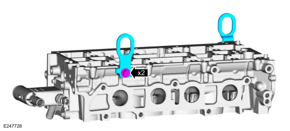
Remove the bolts and the LH and RH engine lift eyes.
 |
-
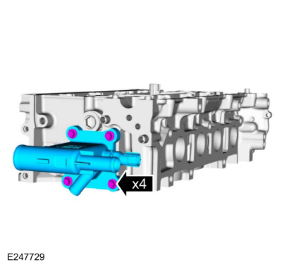
Remove the bolts and coolant outlet.
 |
-
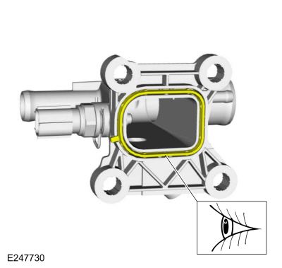
Inspect the coolant outlet gasket and replace if damaged.
 |
-
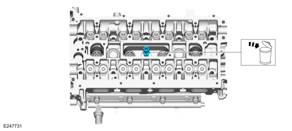
Remove and discard the CHT sensor.
 |
-
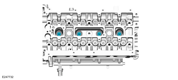
NOTICE: Only use hand tools when removing the spark plugs, or damage can occur to the cylinder head or spark plug.
NOTE: Use compressed air to remove any foreign material in the spark plug well before removing the spark plugs.
Remove the spark plugs.
 |
-
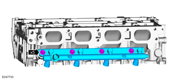
NOTICE: Pull out the fuel rails in the direction of the fuel injector axis or damage may occur to the fuel injectors.
NOTE: Use compressed air and remove any dirt or foreign material from the cylinder head, the engine block and the general surrounding area of the fuel rail and the fuel injectors.
NOTE: When removing the fuel rails, the fuel injectors may remain in the cylinder head and require the use of a Fuel Injector Remover tool to extract. Wiggling the injector by hand to break it loose may allow the injector to be removed by hand.
Remove the bolts and the fuel rail.
 |
-
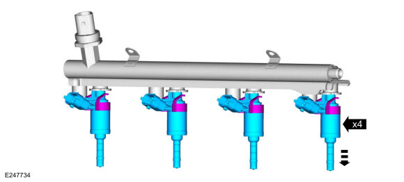
Remove the fuel injectors from the fuel rail.
 |
-
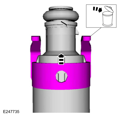
Remove and discard the fuel injector clips.
 |
-
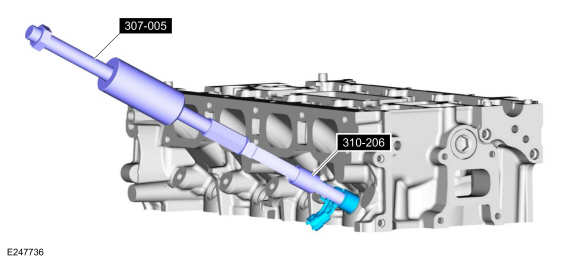
NOTICE: Use minimal force to remove the fuel injectors that remained in the cylinder head with the Fuel Injector Remover tool or damage to the fuel injector assembly may occur. Wiggling the injector by hand to break it loose may allow the injector to be removed by hand.
Using the special tools, remove any of the fuel injectors that remained in the cylinder head.
Use Special Service Tool: 307-005 (T59L-100-B) Slide Hammer. , 310-206-01 Adapter for 310-206.
 |
-
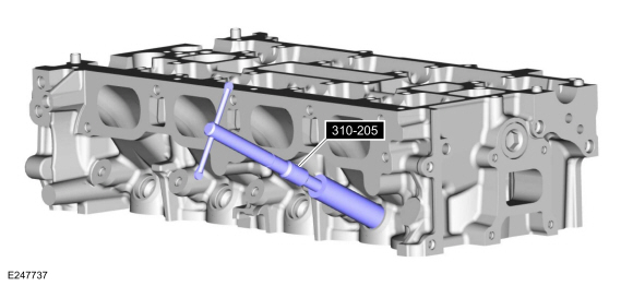
NOTICE: Do not use compressed air to clean the tip of the fuel injector.
NOTICE: Do not use a brush to clean the tip of the fuel injector.
Using the special tool, clean the cylinder head fuel injector bores.
Use Special Service Tool: 310-205 Fuel Injector Brush.
 |
-
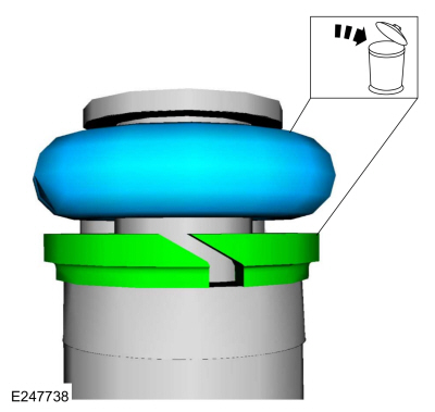
NOTE: Note the correct orientation of the fuel injector support rings, to insure the correct installation of the new fuel injector support rings.
Remove and discard the fuel injector O-rings and fuel injector support rings.
 |
-
NOTICE: Use care when removing the lower Teflon® seals, not to scratch, nick or gouge the fuel injectors.
NOTICE: Do not attempt to cut the lower Teflon® seal without first pulling it away from the fuel injector or damage to the injector may occur.
-
Pull the lower Teflon® seal away from the injector.
-
Carefully cut, remove and discard the lower fuel injector Teflon® seals.
-
Pull the lower Teflon® seal away from the injector.
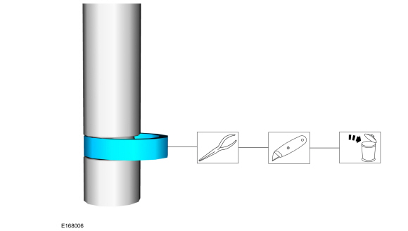 |
-
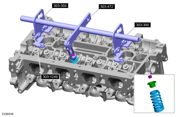
NOTE: Place all parts in order to one side.
NOTE: Remove the valve collet, using some multi-purpose grease and a small screwdriver.
Using the special tools, remove the valve collet, valve spring retainer and the valve spring.
Use Special Service Tool: 303-300 (T87C-6565-A) Set, Valve Spring Compressor. , 303-350 (T89P-6565-A) Compressor, Valve Spring. , 303-472 (T94P-6565-AH) Adapter, Valve Spring Compressor. , 303-1249 Valve Spring Compressor.
Material: Motorcraft® Multi-Purpose Grease Spray / XL-5-A (ESB-M1C93-B)
 |
-
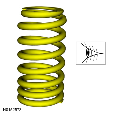
Inspect and install new parts, as necessary.
 |
-
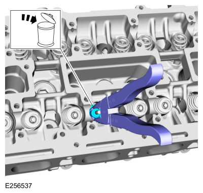
NOTE: Use valve stem seal pliers (such as BeTooll HW0107 or equivalent).
-
Use commercially available valve stem seal pliers to remove the valve stem seal.
-
Discard the valve stem seal.
-
Use commercially available valve stem seal pliers to remove the valve stem seal.
 |
-
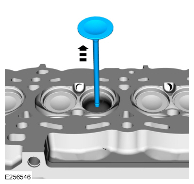
NOTE: Mark each valve location if the original valves are to be used.
Remove the valve.
 |
-
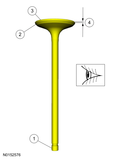
NOTE: Install new parts, as necessary.
-
The end of the stem for grooves or scoring.
-
The valve face and the edge for pits, grooves or scores.
-
The valve head for signs of burning, erosion, warpage and cracking.
-
The valve margin for wear.
-
The end of the stem for grooves or scoring.
 |
-
Repeat the appropriate removal steps for all of the other valves.
ASSEMBLY
-
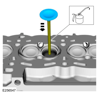
NOTE: If installing the original valves, make sure the valves are installed in the same position from which they were removed.
Coat the valve stems with clean engine oil and install the valve.
 |
-
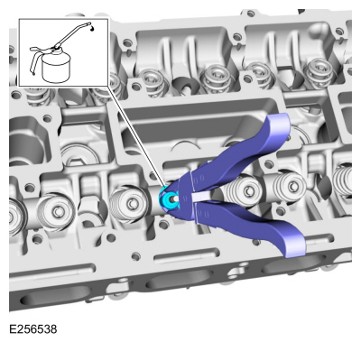
NOTE: Use valve stem seal pliers (such as BeTooll HW0107 or equivalent).
-
Lubricate the valve stem seal with clean engine oil.
-
Use commercially available valve stem seal pliers to install the valve stem seal.
-
Lubricate the valve stem seal with clean engine oil.
 |
-
NOTE: Install the valve collet, using some multi-purpose grease and a small screwdriver.
NOTE: Check the seating of the valve collet.
Using the special tools, install the valve spring, valve spring retainer and the valve collet.
Use Special Service Tool: 303-300 (T87C-6565-A) Set, Valve Spring Compressor. , 303-350 (T89P-6565-A) Compressor, Valve Spring. , 303-472 (T94P-6565-AH) Adapter, Valve Spring Compressor. , 303-1249 Valve Spring Compressor.
Material: Motorcraft® Multi-Purpose Grease Spray / XL-5-A (ESB-M1C93-B)
 |
-
Repeat the appropriate installation steps for all of the other valves.
-
NOTICE: Do not lubricate the new lower Teflon® fuel injector seals.
-
Install the Teflon® Seal Guide onto the fuel injector tip.
Use Special Service Tool: 310-207 Installer, Fuel Injector Seal Assembly.
-
NOTICE: Once the Teflon® seal is installed on the Teflon® Seal Guide, it should immediately be installed onto the fuel injector to avoid excessive expansion of the Teflon® seal.
NOTE: Make sure that new lower fuel injector Teflon® seals are installed.
Install the new Teflon® seals onto the Teflon® Seal Guide, using the Pusher Tool, slide the Teflon® seals along the Teflon® Seal Guide.
-
Using the Pusher Tool, slide the Teflon® seals off
of the Teflon® Seal Guide and into the groove on the fuel injectors.
Use Special Service Tool: 310-207 Installer, Fuel Injector Seal Assembly.
-
Remove the special tools.
-
Install the Teflon® Seal Guide onto the fuel injector tip.
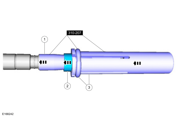 |
-
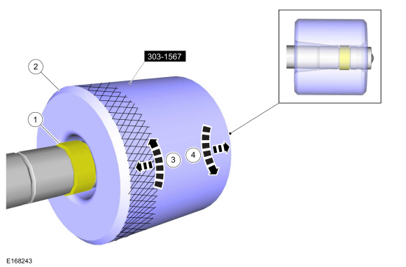
NOTE: Make sure the Teflon® seal is fully seated in the groove on the fuel injector before sizing the Teflon® seal.
-
Massage and warm the Teflon® seal with your fingers
before the Teflon® seal sizer tool is installed. This will aid in
installing the Teflon® seal sizer tool.
-
Position the Teflon® seal sizer tool with the larger
opening towards the Teflon® seal. Push while turning the Teflon® seal
sizer tool 180 degrees.
Use Special Service Tool: 303-1567 Sizer, Teflon Seal.
-
Once the Teflon® seal sizer tool is installed, check
and make sure the Teflon® seal is in the sizing portion of the Teflon®
seal sizer tool.
-
After one minute, turn the Teflon® seal sizer tool back 180 degrees and remove.
-
Massage and warm the Teflon® seal with your fingers
before the Teflon® seal sizer tool is installed. This will aid in
installing the Teflon® seal sizer tool.
 |
-
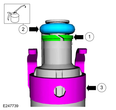
NOTE: Make sure that new fuel injector support rings and new fuel injector O-ring seals are installed.
-
NOTICE: The new the fuel injector support rings must be installed in the correct orientation with the wide surface area facing up against the fuel injector O-ring seals. Improperly installed support rings may cause the fuel system to leak.
Install the new the fuel injector support rings.
-
NOTICE: Use fuel injector O-ring seals that are made of special fuel-resistant material. The use of ordinary O-ring seals may cause the fuel system to leak. Do not reuse the O-ring seals.
NOTE: Do not lubricate the new lower Teflon® fuel injector seals.
Install the new fuel injector O-ring seals and lubricate them with clean engine oil.
-
Install the new the fuel injector clips.
-
 |
-
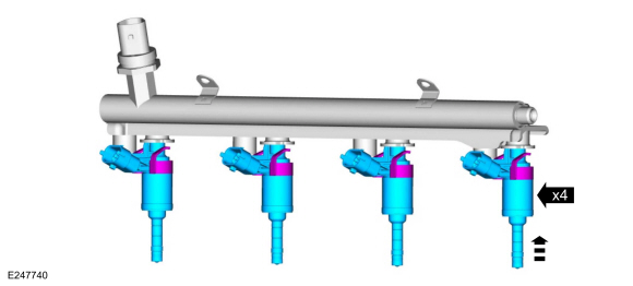
NOTICE: The FRP sensor must be replaced if it is removed from the fuel rail.
NOTE: The anti-rotation finger of the fuel injector must slip into the groove of the fuel rail cup.
Install the fuel injectors to the fuel rail.
 |
-
NOTE: Do not lubricate the new lower Teflon® fuel injector seals.
NOTE: No sudden impact force is allowed.
-
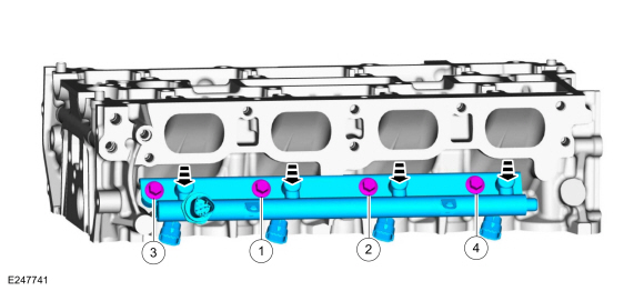
Press the fuel rail down into the cylinder head
injector bores by hand, then install and hand start fuel rail bolts 3
and 4. Release the force before tightening.
-
Release the force before tightening.
-
Install the remaining fuel rail bolts. Tighten all of the fuel rail bolts in the sequence shown.
Torque: 18 lb.ft (25 Nm)
-
Press the fuel rail down into the cylinder head
injector bores by hand, then install and hand start fuel rail bolts 3
and 4. Release the force before tightening.
 |
-
NOTICE: Only use hand tools when installing the spark plugs, or damage can occur to the cylinder head or spark plug.
Install the spark plugs.
Torque: 133 lb.in (15 Nm)
 |
-
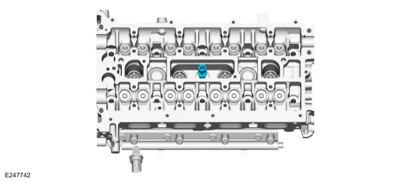
Install the new CHT sensor.
 |
-
NOTE: Install the gasket.
Install the coolant outlet and the bolts.
Torque: 89 lb.in (10 Nm)
 |
-
Install the LH and RH engine lift eyes and the bolts.
Torque: 39 lb.ft (53 Nm)
 |
 Disassembly and Assembly of Subassemblies - Piston
DISASSEMBLY
Remove the piston rings and discard.
Remove the piston pin retainers and discard...
Other information:
Ford Ecosport 2014-2026 Service and Repair Manual: Diagnosis and Testing - Pinpoint Test - DTC: AN, Vehicles With: Rear Seat Side Airbag
U0140:87 Normal Operation and Fault Conditions The BECMB uses information contained in messages from the BCM sent on the HS-CAN1 . DTC Fault Trigger Conditions DTC Description Fault Trigger Conditions U0140:87 Lost Communication with Body Control Module: Missing Message ..
Ford Ecosport 2014-2026 Service and Repair Manual: Removal and Installation - Rear Floor Panel Reinforcement
Special Tool(s) / General Equipment 8 mm Drill Bit MIG/MAG Welding Equipment Spot Weld Drill Bit Locking Pliers Removal NOTE: Factory welds may be substituted with resistance or metal inert gas (MIG) plug welds. Resistance welds may not be placed directly over original location. They must be placed adjacent to original location and match factor..


