Ford Ecosport: Suspension System - General Information / Diagnosis and Testing - Suspension System - FWD
Preliminary Inspection
-
Road test the vehicle.
-
If any suspension alignment or ride height concerns are present, REFER to Symptom Chart: Suspension System.
-
Verify the customer concern by carrying out a road test
on a smooth road. If any vibrations are present, REFER to Symptom Chart:
NVH .
-
If any suspension alignment or ride height concerns are present, REFER to Symptom Chart: Suspension System.
-
Inspect the tires.
-
Check the tire pressures with all normal loads in the vehicle and the tires cold. REFER to the VC label.
-
Verify that all tires are sized to specification. REFER to the VC label.
-
Inspect the tires for incorrect wear and damage. INSTALL new tires as necessary.
-
Check the tire pressures with all normal loads in the vehicle and the tires cold. REFER to the VC label.
-
Inspect the chassis and underbody.
-
Remove any excessive accumulation of mud, dirt or road deposits from the chassis and underbody.
-
Front or rear suspension components.
-
Suspension fastener(s).
-
Incorrect spring usage Spring(s).
-
Shock absorber(s).
-
Strut(s).
-
Suspension bushing(s).
-
Steering system components.
-
Wheel bearing and wheel hub(s).
-
Remove any excessive accumulation of mud, dirt or road deposits from the chassis and underbody.
-
Inspect for aftermarket equipment.
-
Check for aftermarket changes to the steering,
suspension, and wheel and tire components (such as competition or heavy
duty). The specifications shown in this manual do not apply to vehicles
equipped with aftermarket equipment.
-
Check for aftermarket changes to the steering,
suspension, and wheel and tire components (such as competition or heavy
duty). The specifications shown in this manual do not apply to vehicles
equipped with aftermarket equipment.
Symptom Chart: Suspension System
Diagnostics in this manual assume a certain skill level and knowledge of Ford-specific diagnostic practices.
REFER to: Diagnostic Methods (100-00 General Information, Description and Operation).
NOTE: Vehicles equipped with Lane Departure Warning System. The system must be turned OFF before beginning diagnosis.
| Condition | Possible Sources | Actions |
|---|---|---|
| Vehicle drifts/pulls | Refer to the Diagnostic Routine. |
REFER to the symptom chart.  Click here to access Guided Routine (EPAS).
|
| Wander | Overloaded, unevenly or incorrectly loaded vehicle | NOTIFY the customer of incorrect vehicle loading. |
| Ball joint(s) |
CARRY OUT a ball joint inspection. INSTALL new control arm(s) as necessary. REFER to: Lower Arm (204-01 Front Suspension, Removal and Installation). |
|
| Damaged or missing front strut mount bearing(s) |
INSTALL a new front strut mount bearing(s) as necessary. REFER to: Front Strut and Spring Assembly (204-01 Front Suspension, Removal and Installation). |
|
| Loose, worn or damaged front wheel bearing(s) |
INSPECT the wheel bearings. INSTALL new wheel bearings as necessary. REFER to: Front Wheel Bearing and Wheel Hub (204-01 Front Suspension, Removal and Installation). |
|
| Loose, worn or damaged suspension component(s) | INSTALL new suspension component(s) as necessary. | |
| Loose suspension fasteners | INSPECT the suspension fasteners. TIGHTEN to specifications. | |
| Steering components | INSPECT the steering system. INSTALL new components as necessary. | |
| Wheel alignment (excessive total front toe out) |
ADJUST as necessary. REFER to: Front Toe Adjustment (204-00 Suspension System - General Information, General Procedures). |
|
| Front bottoming or riding low | Worn, damaged or incorrect springs |
MEASURE the ride height. REFER to: Ride Height Measurement (204-00 Suspension System - General Information, General Procedures). INSTALL new springs as necessary. REFER to: Front Strut and Spring Assembly (204-01 Front Suspension, Removal and Installation). |
| Worn front strut(s) |
INSTALL new struts as necessary. REFER to: Front Strut and Spring Assembly (204-01 Front Suspension, Removal and Installation). |
|
| Abnormal/incorrect tire wear | Incorrect tire pressure (rapid center rib or inner and outer edge wear) | ADJUST the tire pressure. REFER to VC label. |
| Incorrect tire rotation intervals | REFER to Owners Literature for correct tire rotation intervals. | |
|
INSPECT the wheels and tires. REFER to: Wheel and Tire (204-04A Wheels and Tires, Removal and Installation). |
|
| Front or rear suspension components | INSPECT the front and rear suspension system. REPAIR or INSTALL new suspension components as necessary. | |
| Sticky steering, poor returnability | Damaged or worn front strut mount bearing(s) |
INSTALL a new front strut mount bearing(s) as necessary. REFER to: Front Strut and Spring Assembly (204-01 Front Suspension, Removal and Installation). |
| Binding ball joints |
CARRY OUT a ball joint inspection. INSTALL new control arm(s) as necessary. REFER to: Lower Arm (204-01 Front Suspension, Removal and Installation). |
|
| Steering components |
INSPECT the steering system. INSTALL new components as necessary. Symptom Chart(s) REFER to: Power Steering (211-02 Power Steering, Diagnosis and Testing). |
|
| Steering wheel off-center | Unequal front or rear toe setting (side-to-side) |
CHECK the wheel alignment. REFER to: Front Toe Adjustment (204-00 Suspension System - General Information, General Procedures). |
| Steering components | INSPECT the steering system. INSTALL new components as necessary. | |
| Sway or roll | Overloaded, unevenly or incorrectly loaded vehicle | NOTIFY the customer of incorrect vehicle loading. |
| Loose wheel nut(s) |
TIGHTEN the wheel nut(s) to specification. REFER to: Wheel and Tire (204-04A Wheels and Tires, Removal and Installation). |
|
| Strut(s) or shock absorber(s) |
INSTALL new struts or shock absorbers as necessary. REFER to: Front Strut and Spring Assembly (204-01 Front Suspension, Removal and Installation). or REFER to: Rear Shock Absorber (204-02A Rear Suspension - FWD, Removal and Installation). |
|
| Loose stabilizer bracket-to-frame bolts |
TIGHTEN the bolts to specification. REFER to: Front Stabilizer Bar (204-01 Front Suspension, Removal and Installation). |
|
| Worn stabilizer bar bushings or links |
INSTALL new stabilizer bar bushings or links as necessary. REFER to: Front Stabilizer Bar Bushing (204-01 Front Suspension, Removal and Installation). or REFER to: Front Stabilizer Bar Link (204-01 Front Suspension, Removal and Installation). |
|
| Damaged or broken stabilizer bar |
INSTALL a new stabilizer bar as necessary. REFER to: Front Stabilizer Bar (204-01 Front Suspension, Removal and Installation). |
|
| Worn spring(s) |
INSTALL new springs as necessary. REFER to: Front Strut and Spring Assembly (204-01 Front Suspension, Removal and Installation). or REFER to: Spring (204-02A Rear Suspension - FWD, Removal and Installation). |
|
| Vehicle leans to one side | Unevenly loaded or overloaded vehicle | NOTIFY the customer of incorrect vehicle loading. |
| Front or rear suspension components | INSPECT the front and rear suspension systems. INSTALL new suspension components as necessary. | |
| Incorrect drive axle(s) ride height. Side-to-side lean out of specification |
MEASURE the ride height. REFER to: Ride Height Measurement (204-00 Suspension System - General Information, General Procedures). INSPECT the front and rear suspension systems. REPAIR or INSTALL new components as necessary |
- If an obvious cause for an observed or reported condition is found, correct the cause (if possible) before proceeding to the next step.
- If the fault is not visually evident, REFER to Symptom Chart or REFER to Symptom Chart: NVH .
Symptom Chart: NVH
Diagnostics in this manual assume a certain skill level and knowledge of Ford-specific diagnostic practices.
REFER to: Diagnostic Methods (100-00 General Information, Description and Operation).
NVH
symptoms should be identified using the diagnostic tools that are
available. For a list of these tools, an explanation of their uses and a
glossary of common terms, Glossary of Terms
REFER to: Noise, Vibration and Harshness (NVH) (100-04 Noise, Vibration and Harshness, Description and Operation).
Since it is possible any one of multiple systems may be the cause of a
symptom, it may be necessary to use a process of elimination type of
diagnostic approach to pinpoint the responsible system. If this is not
the causal system for the symptom, REFER to: Noise, Vibration and
Harshness (NVH) (100-04 Noise, Vibration and Harshness, Diagnosis and
Testing).
for the next likely system and continue diagnosis.
Additional diagnostics may be necessary to further isolate the concern. An electronic listening tool such as Chassis Ear® may be used. Follow the tool manufacturer’s instructions and the Possible Sources found in the following NVH chart to determine the connection points.
| Condition | Possible Sources | Actions |
|---|---|---|
| Front suspension noise — a crunch or creaking noise. Occurs mostly during turns over bumps. | Spring upper mount bearing |
REPLACE the strut upper mount bearing and the strut bearing plate. REFER to: Front Strut and Spring Assembly (204-01 Front Suspension, Removal and Installation). |
| Strut bearing plate | ||
| Front suspension noise — a squeak, creak or rattle noise. Occurs mostly over bumps or rough roads due to the suspension moving in an up/down motion. | Strut top nut |
INSPECT and TIGHTEN to specification. REFER to: Front Strut and Spring Assembly (204-01 Front Suspension, Removal and Installation). |
| Jounce bumper | INSPECT, LUBRICATE or INSTALL new components as necessary. | |
| Stabilizer bar insulators and/or Stabilizer bar links |
INSPECT for out-of-position bushings,
isolators or locating pins. INSTALL new components as necessary. REFER to: Front Stabilizer Bar Bushing (204-01 Front Suspension, Removal and Installation). or REFER to: Front Stabilizer Bar Link (204-01 Front Suspension, Removal and Installation). |
|
| Steering gear and/or Tie rod ends |
INSPECT the steering gear and tie rod ends. INSTALL new components as necessary. REFER to: Power Steering (211-02 Power Steering, Diagnosis and Testing). |
|
| Front brake caliper |
INSPECT the front brake caliper(s). REFER to: Brake System (206-00 Brake System - General Information, Diagnosis and Testing). |
|
| Lower control arm / ball joint |
CARRY OUT a ball joint inspection. INSTALL new control arm(s) as necessary. REFER to: Lower Arm (204-01 Front Suspension, Removal and Installation). |
|
| Hub |
INSPECT hub(s). REPAIR or REPLACE as necessary. REFER to: Front Wheel Bearing and Wheel Hub (204-01 Front Suspension, Removal and Installation). |
|
| Exhaust system |
INSPECT the exhaust system. REFER to: Exhaust System (309-00B Exhaust System - 1.5L Duratec (90kW/120PS) – I3, Diagnosis and Testing). or REFER to: Exhaust System (309-00C Exhaust System - 2.0L Duratec-HE (129kW/175PS), Diagnosis and Testing). or |
|
| Powertrain mounts |
INSPECT the powertrain mounts. REFER to: Engine Mount (303-01C Engine - 2.0L Duratec-HE (129kW/175PS), Removal and Installation). or REFER to: Engine Mount (303-01C Engine - 2.0L Duratec-HE (129kW/175PS), Removal and Installation). or |
|
| Subframe pin(s), welds or insulators |
INSPECT subframe. REPAIR or REPLACE as necessary. REFER to: Front Subframe (502-00 Uni-Body, Subframe and Mounting System, Removal and Installation). |
|
| Rear suspension noise — a squeak, creak or rattle noise. Occurs mostly over bumps or rough roads due to the suspension moving in an up/down motion. | Loose or damaged rear shock absorber(s) or shock absorber bushing(s) |
INSPECT the rear shock absorber(s) or
shock absorber bushing(s). INSTALL new components as necessary. REFER to: Rear Shock Absorber (204-02A Rear Suspension - FWD, Removal and Installation). |
| Damaged spring(s) or spring mount(s) |
INSPECT the rear spring(s) and spring mount(s). REPLACE damaged components as necessary. REFER to: Spring (204-02A Rear Suspension - FWD, Removal and Installation). |
|
| Damaged or worn control arm bushing(s) |
INSPECT the rear control arm bushings. REPLACE damaged or worn components as necessary. REFER to: Lower Arm (204-01 Front Suspension, Removal and Installation). or REFER to: Trailing Arm Bushing (204-02A Rear Suspension - FWD, Removal and Installation). |
|
| Worn or damaged stabilizer bar bushing(s) or link(s) |
INSPECT the stabilizer bar bushing(s) or
link(s). REPLACE damaged or worn components as necessary. or REFER to: Rear Stabilizer Bar Link (204-02B Rear Suspension - AWD, Removal and Installation). or REFER to: Front Stabilizer Bar Bushing (204-01 Front Suspension, Removal and Installation). or REFER to: Front Stabilizer Bar Link (204-01 Front Suspension, Removal and Installation). |
|
| Noise from front suspension when turning — crunch or ratcheting noise. Occurs as a result of the suspension twisting and flexing. | Strut top nut |
INSPECT and TIGHTEN to specification. REFER to: Front Strut and Spring Assembly (204-01 Front Suspension, Removal and Installation). |
| Worn or damaged front strut bearing(s) |
INSPECT for worn or damaged strut bearing. INSTALL new components as necessary. REFER to: Front Strut and Spring Assembly (204-01 Front Suspension, Removal and Installation). |
|
| Coil Spring |
INSPECT springs. REPLACE as necessary. REFER to: Front Strut and Spring Assembly (204-01 Front Suspension, Removal and Installation). |
|
| Strut brackets or seat(s) | INSPECT strut brackets or seat(s). REPAIR as necessary. | |
| Stabilizer bar |
INSPECT the stabilizer bar. REPAIR or REPLACE as necessary. REFER to: Front Stabilizer Bar (204-01 Front Suspension, Removal and Installation). |
|
| Steering gear |
INSPECT the steering gear. REFER to: Power Steering (211-02 Power Steering, Diagnosis and Testing). |
|
| Tie rod ends |
INSPECT tie rod ends. INSTALL new components as necessary. REFER to: Tie Rod (211-02 Power Steering, Removal and Installation). |
|
| Hub |
INSPECT hub(s). REPAIR or REPLACE as necessary. REFER to: Front Wheel Bearing and Wheel Hub (204-01 Front Suspension, Removal and Installation). |
|
| Lower control arm / ball joint |
CARRY OUT a ball joint inspection. INSTALL new control arm(s) as necessary. REFER to: Lower Arm (204-01 Front Suspension, Removal and Installation). |
|
| Noise from front suspension when turning — Crunch clunk or grunt noise from the front suspension occurring when turning to full left or right stop. | Steering stops | Normal condition. No action required. |
| Noise while braking — Noises occurring during this condition result from rearward and downward force applied to the suspension and subframe such as rearward force applied to the lower control arm. | Front brake caliper |
INSPECT the front brake caliper(s). REFER to: Brake System (206-00 Brake System - General Information, Diagnosis and Testing). |
| Hub |
INSPECT hub(s). REPAIR or REPLACE as necessary. REFER to: Front Wheel Bearing and Wheel Hub (204-01 Front Suspension, Removal and Installation). |
|
| Subframe insulators |
INSPECT subframe. REPAIR or REPLACE as necessary. REFER to: Front Subframe (502-00 Uni-Body, Subframe and Mounting System, Removal and Installation). |
|
| Lower control arm / ball joint |
CARRY OUT a ball joint inspection. INSTALL new control arm(s) as necessary. REFER to: Lower Arm (204-01 Front Suspension, Removal and Installation). |
|
| Powertrain mounts |
INSPECT the powertrain mounts. REFER to: Engine Mount (303-01C Engine - 2.0L Duratec-HE (129kW/175PS), Removal and Installation). or REFER to: Engine Mount (303-01C Engine - 2.0L Duratec-HE (129kW/175PS), Removal and Installation). or |
|
| Roll restrictor |
INSPECT the roll restrictor. REPAIR or REPLACE as necessary. REFER to: Roll Restrictor RH - 1.5L Duratec (90kW/120PS) – I3 (307-01A Automatic Transmission - 6-Speed Automatic Transmission – 6F15, Removal and Installation). or REFER to: Roll Restrictor RH (307-01B Automatic Transmission - 6-Speed Automatic Transmission – 6F35, Removal and Installation). or REFER to: Roll Restrictor RH (308-03 Manual Transmission - 5-Speed Manual Transmission – B5/IB5, Removal and Installation). |
|
| Noise while accelerating — Noises occurring during this condition result from powertrain torque and flex, such as torque on the powertrain mounts during acceleration. | Body (inner fender, bulkhead, seams and pinch welds) | INSPECT and REPAIR as necessary. |
| Hub |
INSPECT hub(s). REPAIR or REPLACE as necessary. REFER to: Front Wheel Bearing and Wheel Hub (204-01 Front Suspension, Removal and Installation). |
|
| Powertrain mounts |
INSPECT the powertrain mounts. REFER to: Engine Mount (303-01C Engine - 2.0L Duratec-HE (129kW/175PS), Removal and Installation). or REFER to: Engine Mount (303-01C Engine - 2.0L Duratec-HE (129kW/175PS), Removal and Installation). or |
|
| Roll restrictor |
INSPECT the roll restrictor. REPAIR or REPLACE as necessary. REFER to: Roll Restrictor RH - 1.5L Duratec (90kW/120PS) – I3 (307-01A Automatic Transmission - 6-Speed Automatic Transmission – 6F15, Removal and Installation). or REFER to: Roll Restrictor RH (307-01B Automatic Transmission - 6-Speed Automatic Transmission – 6F35, Removal and Installation). or REFER to: Roll Restrictor RH (308-03 Manual Transmission - 5-Speed Manual Transmission – B5/IB5, Removal and Installation). |
|
| Exhaust system |
INSPECT the exhaust system. REFER to: Exhaust System (309-00B Exhaust System - 1.5L Duratec (90kW/120PS) – I3, Diagnosis and Testing). or REFER to: Exhaust System (309-00C Exhaust System - 2.0L Duratec-HE (129kW/175PS), Diagnosis and Testing). or |
|
| Subframe pin(s), welds or insulators |
INSPECT subframe. REPAIR or REPLACE as necessary. REFER to: Front Subframe (502-00 Uni-Body, Subframe and Mounting System, Removal and Installation). |
|
| Noise while entering driveways or driving over dips or depressions — Noises occurring during this condition result from the body , subframe or suspension twisting or flexing such as the tension on body structure welds. | Body (inner fender, bulkhead, seams and pinch welds) | INSPECT and REPAIR as necessary. |
| Stabilizer bar links |
INSPECT the stabilizer bar links. INSTALL new stabilizer bar links as necessary. REFER to: Front Stabilizer Bar Bushing (204-01 Front Suspension, Removal and Installation). or REFER to: Front Stabilizer Bar Link (204-01 Front Suspension, Removal and Installation). |
|
| Subframe pin(s), welds or insulators |
INSPECT subframe. REPAIR or REPLACE as necessary. REFER to: Front Subframe (502-00 Uni-Body, Subframe and Mounting System, Removal and Installation). |
|
| Clunk or pop or thump/thud — noise may be thought of as a loose part striking an adjacent part or a secure part coming loose when force is applied. A clunk is often rhythmic, repeatable and metallic in nature. | Loose fasteners | INSPECT for loose nuts or bolts. |
| Worn or damaged bushings | INSPECT for out-of-position or damaged components. | |
| Struts & shocks |
INSPECT for worn or damaged struts or shocks. REPLACE as necessary. REFER to: Front Strut and Spring Assembly (204-01 Front Suspension, Removal and Installation). or REFER to: Rear Shock Absorber (204-02A Rear Suspension - FWD, Removal and Installation). |
|
| Coil spring or spring seat out of position | INSPECT for out-of-position or damaged components. ADJUST or REPLACE as necessary. | |
| Worn or damaged ball joint(s) |
CARRY OUT a ball joint inspection. INSTALL new control arm(s) as necessary. REFER to: Lower Arm (204-01 Front Suspension, Removal and Installation). |
|
| Rattle — noise occurs mostly over bumps, rough roads or uneven surfaces at low speeds (i.e. parking lot). A rattle is often a rapid, repetitive noise that can be metallic or non-metallic in nature. |
|
INSPECT for loose nuts or bolts. TIGHTEN to specification. INSPECT for out-of-position or damaged components. ADJUST or INSTALL new components as necessary. |
| Whine, roar or groan — noise generally occurs over 30 mph and is often more noticeable with steering input. | Loose or damaged wheel bearings |
INSPECT the front or rear wheel bearing(s). INSTALL new bearing(s) as necessary. REFER to: Front Wheel Bearing and Wheel Hub (204-01 Front Suspension, Removal and Installation). |
| Shimmy | Loose wheel nut(s) |
TIGHTEN the nut(s) to specification. REFER to: Wheel and Tire (204-04A Wheels and Tires, Removal and Installation). |
| Loose front suspension fastener(s) | TIGHTEN the fastener(s) to specifications. | |
| Loose front wheel bearing(s) |
INSPECT the front wheel bearing(s). INSTALL new bearing(s) as necessary. REFER to: Front Wheel Bearing and Wheel Hub (204-01 Front Suspension, Removal and Installation). |
|
| Strut(s) or shock absorber(s) |
INSTALL new struts or shock absorbers as necessary. REFER to: Front Strut and Spring Assembly (204-01 Front Suspension, Removal and Installation). REFER to: Rear Shock Absorber (204-02A Rear Suspension - FWD, Removal and Installation). |
|
| Shimmy — most noticeable on coast/deceleration. Also hard steering condition | Excessive positive caster | INSPECT the front suspension. REPAIR or INSTALL new suspension components as necessary. |
| Rough/harsh ride | Incorrect tire pressure | ADJUST the tire pressure. REFER to VC label. |
| Strut(s) or shock absorber(s) |
INSTALL new struts or shock absorbers as necessary. REFER to: Front Strut and Spring Assembly (204-01 Front Suspension, Removal and Installation). REFER to: Rear Shock Absorber (204-02A Rear Suspension - FWD, Removal and Installation). |
|
| Spring(s) |
MEASURE the ride height. REFER to: Ride Height Measurement (204-00 Suspension System - General Information, General Procedures). INSTALL new springs as necessary. REFER to: Front Strut and Spring Assembly (204-01 Front Suspension, Removal and Installation). or REFER to: Spring (204-02A Rear Suspension - FWD, Removal and Installation). |
|
| Damaged suspension component(s) | INSTALL new suspension component(s) as necessary. |
Component Tests
Ball Joint Inspection
-
Prior to inspecting the ball joints for wear, inspect
the wheel bearings. Install a new wheel bearing as necessary. Wheel
Bearing and Wheel Hub
REFER to: Front Wheel Bearing and Wheel Hub (204-01 Front Suspension, Removal and Installation).
-
NOTE: In order to obtain accurate measurements, the suspension must be in full rebound with the weight of the vehicle supported by the frame.
Raise and support the vehicle by the frame to allow the wheels to hang in the rebound position.
-
Inspect the ball joint and ball joint boot for damage.
-
If the ball joint or ball joint boot is damaged, install a new lower control arm as necessary.
REFER to: Lower Arm (204-01 Front Suspension, Removal and Installation).
-
If the ball joint or ball joint boot is damaged, install a new lower control arm as necessary.
-
NOTICE: Do not use any tools or equipment to move the wheel and tire assembly or suspension components while checking for relative movement. Suspension damage may occur. The use of tools or equipment will also create relative movement that may not exist when using hand force. Relative movement must be measured using hand force only.
Inspect the ball joint for relative movement by alternately pulling downward and pushing upward on the lower control arm by hand. Note any relative vertical movement between the wheel knuckle and lower control arm at the lower ball joint.
-
If relative movement is not felt or seen, the ball joint is OK. Do not install a new lower control arm.
-
If relative movement is found, continue with Step 5.
-
If relative movement is not felt or seen, the ball joint is OK. Do not install a new lower control arm.
-
NOTE: In order to obtain an accurate measurement, the dial indicator should be aligned as close as possible with the vertical axis (center line) of the ball joint.
To measure ball joint deflection, attach a suitable dial indicator with a flexible arm between the lower control arm and the wheel knuckle or ball joint stud.
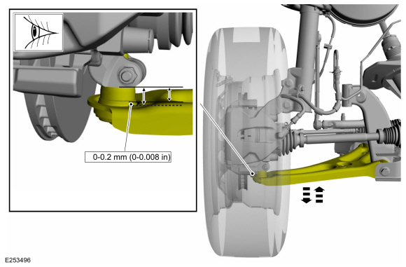
-
Measure the ball joint deflection while an assistant pushes up and pulls down on the lower control arm, by hand.
-
If the deflection exceeds the specification, a new lower control arm must be installed.
REFER to: Lower Arm (204-01 Front Suspension, Removal and Installation).
-
If the deflection meets the specification, no further action is required.
-
If the deflection exceeds the specification, a new lower control arm must be installed.
 Specifications
General Specifications
Item
Specification
Ball Joint Deflection
Lower
0-0...
 Diagnosis and Testing - Suspension System - AWD
Special Tool(s)
Alignment Pins, Subframe205-870
Adapter for 205-870205-870-01
Inspection and Verification
Verify the customer concern...
Other information:
Ford Ecosport 2014-2026 Service and Repair Manual: Removal and Installation - Oil Pan
Special Tool(s) / General Equipment Oil Drain Equipment Materials Name Specification Motorcraft® Threadlock and SealerTA-25-B - Motorcraft® Silicone Gasket and SealantTA-30 WSE-M4G323-A4 Removal LHD 4WD/LHD FWD ..
Ford Ecosport 2014-2026 Service and Repair Manual: Description and Operation - Low/Reverse Clutch Assembly
Low/Reverse Clutch Exploded View Item Description 1 Transmission case 2 Low One-Way Clutch (OWC) 3 Rear planetary carrier 4 Low/reverse clutch pressure plate 5 Low/reverse clutch 6 Low/reverse clutch wav..
Categories
- Manuals Home
- 2nd Gen Ford Ecosport Service Manual (2014 - 2026)
- Diagnosis and Testing - Evaporative Emissions
- Body and Paint
- Description and Operation - Evaporative Emissions - System Operation and Component Description
- Service Information
- Removal and Installation - Front Seat
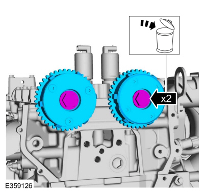
Removal and Installation - Variable Camshaft Timing (VCT) Unit
Removal
NOTICE: During engine repair procedures, cleanliness is extremely important. Any foreign material, including any material created while cleaning gasket surfaces, that enters the oil passages, coolant passages or the oil pan can cause engine failure.
Remove the timing chain.Refer to: Timing Chain (303-01C Engine - 2.0L Duratec-HE (129kW/175PS), Removal and Installation).
Remove the bolts and VCT units.
Discard the bolts.