Refer to Wiring Diagrams Cell 20 for schematic and connector information.
Normal Operation and Fault Conditions
REFER to: Starting System - System Operation and Component Description
(303-06C Starting System - 2.0L Duratec-HE (129kW/175PS), Description
and Operation).
DTC Fault Trigger Conditions
| DTC |
Description |
Fault Trigger Condition |
| PCM P06E9:00 |
Engine Starter Performance: No Sub Type Information |
The PCM sets this DTC when no engine rotation is detected during a crank event.
|
Possible Sources
- Battery
- Battery cables
-
IPC
- Starter motor
-
BJB starter relay
Visual Inspection and Pre-checks
- Inspect the run/start relay.
- Inspect the high current BJB connections.
- Verify the BJB fuse 36 (30A).
- Inspect the passive key.
|
| B1 PERFORM INSPECTION AND VERIFICATION |
-
NOTE:
Make sure battery voltage is greater than 12.2 volts prior to and during this pinpoint test.
NOTE:
If it is necessary to leave the battery charger
connected during testing, do not leave it on its highest or boost
setting. The highest settings can exceed 16 volts, resulting in false
test results and setting of DTCs.
Perform Inspection and Verification procedure in this section.
Was an obvious cause for an observed or reported concern found?
| Yes |
CORRECT the cause as necessary.
|
|
| B2 CHECK FOR NO KEY DETECTED MESSAGE IN THE MESSAGE CENTER |
-
NOTE:
There are certain areas inside the vehicle where
the passive key may not be detected and the message center displays NO
KEY DETECTED. If the passive key is in the far outside edges of the
interior (like in a door map pocket or above a sun visor) it might not
be detected. Move the passive key to a different location and try to
start the vehicle again.
Check the message displayed in the message center while pressing the ignition switch - push button start.
Is NO KEY DETECTED displayed?
| Yes |
DIAGNOSE the NO KEY DETECTED concern.
REFER to: Passive Anti-Theft
System (PATS) (419-01B Passive Anti-Theft System (PATS) - Vehicles
Without: Keyless Entry and Push Button Start, Diagnosis and Testing).
|
|
| B3 VERIFY THE BCM (BODY CONTROL MODULE)
, IPC (INSTRUMENT PANEL CLUSTER)
AND PCM (POWERTRAIN CONTROL MODULE)
PASS THE NETWORK TEST |
-
Using a diagnostic scan tool, perform the Network Test.
Did the BCM , IPC and PCM pass the Network Test?
| No |
REFER to: Communications Network (418-00
Module Communications Network - 2.0L Duratec-HE (129kW/175PS), 2.0L
Duratec-HE (125kW/170PS) – MI4, 2.0L Duratec-HE Flex Fuel (129kW/175PS))
.
|
|
| B4 RETRIEVE BCM (BODY CONTROL MODULE)
DIAGNOSTIC TROUBLE CODES (DTCS) |
-
Using a diagnostic scan tool, perform BCM self-test.
Are any BCM Diagnostic Trouble Codes (DTCs) present?
| Yes |
For all BCM Diagnostic Trouble Codes (DTCs), REFER to the BCM DTC Chart in this section.
|
|
| B5 RETRIEVE PCM (POWERTRAIN CONTROL MODULE)
DIAGNOSTIC TROUBLE CODES (DTCS) |
-
Using a diagnostic scan tool, perform PCM self-test.
Are any PCM Diagnostic Trouble Codes (DTCs) other than P06E9 present?
| Yes |
REFER to the PCM DTC Chart in this section.
|
|
| B6 CHECK THE OPERATION OF THE STOPLAMPS |
-
While observing the stoplamps, apply the brake pedal.
Do the stoplamps illuminate?
| No |
DIAGNOSE All the Stoplamps are inoperative.
REFER to: Stoplamps (417-01 Exterior Lighting, Diagnosis and Testing).
|
|
| B7 CHECK THE BRAKE PEDAL POSITION (BOO1) PID (PARAMETER IDENTIFICATION)
|
-
Using a diagnostic scan tool, view PCM Parameter Identifications (PIDs).
-
Monitor the PCM B001 PID while applying the brake pedal.
Does the PID read On?
|
| B8 CHECK THE BPP (BRAKE PEDAL POSITION)
SWITCH CIRCUIT FOR VOLTAGE AT THE PCM (POWERTRAIN CONTROL MODULE)
|
-
While applying the brake pedal, measure:
Click to display connectors
|
Positive Lead
|
Measurement / Action
|
Negative Lead
|
|
C1915B-12
|

|
Ground
|
Is the voltage greater than 11 volts?
|
| B9 CHECK BCM (BODY CONTROL MODULE)
IGN_FINAL PID (PARAMETER IDENTIFICATION)
|
-
Using a diagnostic scan tool, view the BCM Parameter Identifications (PIDs).
-
Make sure the transmission is in PARK or NEUTRAL.
-
Monitor the BCM
PID IGN_FINAL while pressing the ignition switch - push button start and the brake pedal.
Does the PID change from Off to Start when the ignition switch - push button start and brake pedal are pressed?
| No |
DIAGNOSE No power in ON.
REFER to: Steering Wheel and Column
Electrical Components (211-05 Steering Wheel and Column Electrical
Components, Diagnosis and Testing).
|
|
| B10 CHECK THE PCM (POWERTRAIN CONTROL MODULE)
IN GEAR-TRANSMISSION IS APPLYING A LOAD TO ENGINE (IN_GEAR) PID (PARAMETER IDENTIFICATION)
|
-
Using a diagnostic scan tool, view the PCM Parameter Identifications (PIDs).
-
Monitor the PCM
PID IN_GEAR, while placing the gear selector in PARK and then NEUTRAL.
Does the PID read No in both positions?
| No |
REFER to: Automatic Transmission - 2.0L
Duratec-HE (125kW/170PS) – MI4/2.0L Duratec-HE Flex Fuel (129kW/175PS)
(307-01 Automatic Transmission - 2.0L Duratec-HE (129kW/175PS), 2.0L
Duratec-HE (125kW/170PS) – MI4, 2.0L Duratec-HE Flex Fuel (129kW/175PS))
.
|
|
| B11 CHECK THE PCM (POWERTRAIN CONTROL MODULE)
ENGINE CRANKING (ENG_CRANK) PID (PARAMETER IDENTIFICATION)
|
-
Make sure the transmission is in PARK or NEUTRAL.
-
Using a diagnostic scan tool, view the PCM Parameter Identifications (PIDs).
-
Monitor the PCM
PID ENG_CRANK while pressing the ignition switch - push button start and the brake pedal.
Does the PID change from Inactive to Active?
|
| B12 CHECK THE BJB (BATTERY JUNCTION BOX)
STARTER RELAY FUSE |
-
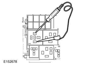
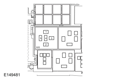
Verify the BJB fuse 36 (30A).
Was the fuse OK?
| No |
REPAIR the circuit for a short to ground.
|
|
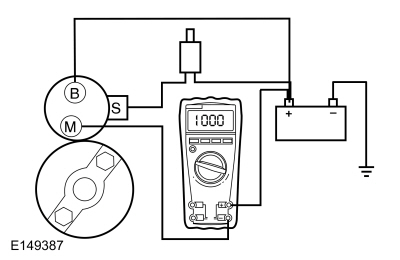
| B13 CHECK FOR START REQUEST AT THE STARTER |
-
Disconnect Starter solenoid C1715B
.
-
While pressing ignition switch - push button start and the brake pedal, measure:
Click to display connectors
|
Positive Lead
|
Measurement / Action
|
Negative Lead
|
|
C1715B-1 ("S" terminal)
|
|
Ground
|
Is the voltage greater than 11 volts?
| No |
Connect Starter solenoid C1715B and GO to B14
|
|
| B14 CHECK THE STARTER RELAY CONTROL OPERATION |
|
NOTICE:
The following step uses a test light to simulate
normal circuit loads. Use only the test light recommended in the Special
Tools table at the beginning of this section. To avoid connector
terminal damage, use the Flex Probe Kit for the test light probe
connection to the vehicle. Do not use the test light probe directly on
any connector.
-
Remove the BJB starter relay.
-
Measure:
|
Positive Lead
|
Measurement / Action
|
Negative Lead
|
 BJB starter relay pin 1
|

|
BJB starter relay pin 2
|
-
Make sure the transmission is in PARK or NEUTRAL.
-
While pressing ignition switch - push button start and the brake pedal, observe the test light.
Does the test light illuminate when pressing ignition switch - push button start and the brake pedal?
|
| B15 CHECK THE VOLTAGE TO THE STARTER RELAY |
-
Measure:
|
Positive Lead
|
Measurement / Action
|
Negative Lead
|
 BJB starter relay pin 3
|
|
Ground
|
Is the voltage greater than 11 volts?
| No |
VERIFY BJB
fuse 36 (30A) is OK. If OK, REPAIR the circuit for an open. If not OK,
REFER to the Wiring Diagrams manual to identify the possible causes of
the circuit short.
|
|
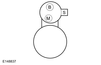
| B16 CHECK THE STARTER MOTOR OPERATION AT THE STARTER |
-
Connect a remote starter switch between the starter solenoid C1715B-1 ("B" terminal) and C1715A-1 ("S" terminal).
-
Make sure the transmission is in PARK or NEUTRAL.
-
Engage the remote starter switch.
Did the starter engage and the engine crank?
| Yes |
INSTALL a new starter relay.
|
|
| B17 CHECK THE STARTER MOTOR FOR CORRECT OPERATION |
-
Perform Starter Motor - Positive Circuit Test in this section.
Was an obvious cause found?
| Yes |
Correct the cause as necessary.
|
|
| B18 CHECK THE BATTERY GROUND CABLES |
-
Measure:
|
Positive Lead
|
Measurement / Action
|
Negative Lead
|
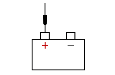
|
|
Ground G115
|
Are the voltages greater than 11 volts?
| No |
CLEAN or INSTALL new negative battery cables as necessary.
REFER to: Battery Cables - 2.0L Duratec-HE (125kW/170PS) – MI4 (414-01 Battery, Mounting and Cables, Removal and Installation).
|
|
| B19 CHECK THE STARTER MOTOR GROUND |
-
Measure:
|
Positive Lead
|
Measurement / Action
|
Negative Lead
|
|
|
|
 Starter motor case
|
Is the voltage greater than 11 volts?
| No |
CLEAN the starter motor mounting flange and MAKE SURE the starter motor is correctly mounted.
REFER to: Starter Motor (303-06C Starting System - 2.0L Duratec-HE (129kW/175PS), Removal and Installation).
|
|
| B20 CHECK THE VOLTAGE TO THE STARTER MOTOR |
-
Measure:
Click to display connectors
|
Positive Lead
|
Measurement / Action
|
Negative Lead
|
|
C1715A-1 ("B" terminal)
|
|
Ground
|
Is the voltage greater than 11 volts?
| No |
INSTALL a new positive battery cable.
REFER to: Battery Cables - 2.0L Duratec-HE (125kW/170PS) – MI4 (414-01 Battery, Mounting and Cables, Removal and Installation).
|
|
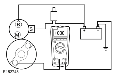
| B21 CHECK FOR START INPUT AT THE STARTER |
-
Connect
BJB starter relay.
-
Disconnect Starter solenoid C1715B
.
-
While pressing ignition switch - push button start and the brake pedal, measure:
Click to display connectors
|
Positive Lead
|
Measurement / Action
|
Negative Lead
|
|
C1715B-1 ("S" terminal)
|
|
Ground
|
Is the voltage greater than 11 volts?
| Yes |
CLEAN the starter solenoid "S" terminal and starter
solenoid connector. CHECK the wiring and the starter motor for a loose
or intermittent connection.
|
| No |
REPAIR the circuit for an open.
|
|
| B22 CHECK THE PCM (POWERTRAIN CONTROL MODULE)
STARTER RELAY CIRCUITS FOR A SHORT TO GROUND |
-
Disconnect
BJB starter relay.
-
Measure:
Click to display connectors
|
Positive Lead
|
Measurement / Action
|
Negative Lead
|
|
C1915B-62
|

|
Ground
|
|
C1915B-43
|
|
Ground
|
Are the resistances greater than 10,000 ohms?
| No |
REPAIR the affected circuit.
|
|
| B23 CHECK THE PCM (POWERTRAIN CONTROL MODULE)
STARTER RELAY CIRCUITS FOR AN OPEN |
-
Measure:
Click to display connectors
|
Positive Lead
|
Measurement / Action
|
Negative Lead
|
|
C175B-1
|
|
BJB starter relay pin 1
|
|
C175B-58
|
|
BJB starter relay pin 2
|
Are the resistances less than 3 ohms?
| No |
REPAIR the affected circuit.
|
|
| B24 CHECK FOR CORRECT PCM (POWERTRAIN CONTROL MODULE)
OPERATION |
-
Disconnect and inspect all PCM connectors.
-
Repair:
-
corrosion (install new connectors or terminals - clean module pins)
-
damaged or bent pins - install new terminals/pins
-
pushed-out pins - install new pins as necessary
-
Reconnect the PCM connectors. Make sure they seat and latch correctly.
-
Operate the system and determine if the concern is still present.
Is the concern still present?
| Yes |
CHECK OASIS for any applicable Technical Service Bulletins (TSBs). If a
TSB exists for this concern, DISCONTINUE this test and FOLLOW the TSB
instructions. If no Technical Service Bulletins (TSBs) address this
concern,
 Click here to access Guided Routine (PCM)..
|
| No |
The system is operating correctly at this time. The
concern may have been caused by module connections. ADDRESS the root
cause of any connector or pin issues.
|
|
| B25 CHECK FOR CORRECT BCM (BODY CONTROL MODULE)
OPERATION |
-
Disconnect and inspect all BCM connectors.
-
Repair:
-
corrosion (install new connectors or terminals - clean module pins)
-
damaged or bent pins - install new terminals/pins
-
pushed-out pins - install new pins as necessary
-
Reconnect the BCM connectors. Make sure they seat and latch correctly.
-
Operate the system and determine if the concern is still present.
Is the concern still present?
| Yes |
CHECK OASIS for any applicable Technical Service Bulletins (TSBs). If a
TSB exists for this concern, DISCONTINUE this test and FOLLOW the TSB
instructions. If no Technical Service Bulletins (TSBs) address this
concern, INSTALL a new BCM .
REFER to: Body Control Module (BCM) (419-10 Multifunction Electronic Modules, Removal and Installation).
|
| No |
The system is operating correctly at this time. The
concern may have been caused by module connections. ADDRESS the root
cause of any connector or pin issues.
|
|

 General Procedures - Starter Motor Drive Gear and Flywheel Ring Gear Inspection