Ford Ecosport: Speed Control / Diagnosis and Testing - Speed Control
Ford Ecosport 2014-2025 Service and Repair Manual / Fuel System / Speed Control / Diagnosis and Testing - Speed Control
Refer to Wiring Diagrams Section 310-03 for schematic and connector information.
General Equipment
| Ford diagnostic equipment |
Inspection and Verification
-
Verify the customer concern by operating the system.
-
Visually inspect for obvious signs of mechanical or electrical damage.
Visual Inspection Chart
| Mechanical | Electrical |
|---|---|
|
|
-
If an obvious cause for an observed or reported concern is
found, correct the cause (if possible) before proceeding to the next
step.
-
If the cause is not visually evident, verify the symptom and
refer to the diagnostic tab within the Ford diagnostic equipment.
 Description and Operation - Speed Control - System Operation and Component Description
System Diagram
Item
Description
1
Control switch unit - cruise control system
2
Clockspring
3
Instrument cluster
4
wheel speed sensor,
5
ABS module
6
TCM
Comments:Vehicles with automatic transaxle...

Other information:
Ford Ecosport 2014-2025 Service and Repair Manual: General Procedures - Battery Drain Check
Check NOTE: No factory-equipped vehicle should have more than a 25 mA (0.025 amp) – 50 mA (0.050) draw depending on the vehicle's accessories. Check for current drains on the battery in excess of 25 mA (0.025 amp) – 50 mA (0.050) with all the electrical accessories off and the vehicle at rest for at least 75 minutes (depending on region). Current drains can be tested with the fo..
Ford Ecosport 2014-2025 Service and Repair Manual: Removal and Installation - Fuel Tank Pressure Sensor and Tube
Removal NOTE: Removal steps in this procedure may contain installation details. With the vehicle in NEUTRAL, position it on a hoist. Refer to: Jacking and Lifting - Overview (100-02 Jacking and Lifting, Description and Operation). Detach the retainers and disconnect the electrical connector. Release the spring lock coupling. ..
Categories
- Manuals Home
- 2nd Gen Ford Ecosport Service Manual (2014 - 2025)
- Removal and Installation - Catalytic Converter
- Climate Control System - General Information
- Removal and Installation - Evaporative Emission Canister Purge Valve
- Removal and Installation - Rear Bumper
- Removal and Installation - Block Heater
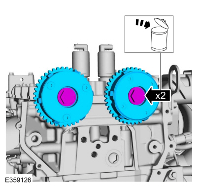
Removal and Installation - Variable Camshaft Timing (VCT) Unit
Removal
NOTICE: During engine repair procedures, cleanliness is extremely important. Any foreign material, including any material created while cleaning gasket surfaces, that enters the oil passages, coolant passages or the oil pan can cause engine failure.
Remove the timing chain.Refer to: Timing Chain (303-01C Engine - 2.0L Duratec-HE (129kW/175PS), Removal and Installation).
Remove the bolts and VCT units.
Discard the bolts.
Copyright © 2025 www.foecosport2.com