Ford Ecosport: Supplemental Restraint System / Diagnosis and Testing - Pinpoint Test - DTC: AL, Vehicles With: Rear Seat Side Airbag
B1142:62, B11D9:13, B13BF:14
Refer to Wiring Diagrams Cell 46 for schematic and connector information.
Normal Operation and Fault Conditions
The BECMB provides battery voltage to the RCM and OCSM . The BECMB compares HS-CAN1 messages to ignition voltage inputs. If the status of the HS-CAN1 message and the voltage input do not match, the BECMB sets a DTC .
If a fault is detected, the BECMB stores the appropriate DTC in memory and sends a message to the RCM over HS-CAN1 and HS-CAN2 , indicating that a BECMB fault is present. Upon receipt of this message, the RCM sets DTC U0413:92 and sends a message to the IPC to illuminate the airbag warning indicator.
DTC Fault Trigger Conditions
| DTC | Description | Fault Trigger Conditions |
|---|---|---|
| B1142:62 | Ignition Status 1: Signal Compare Failure | A fault is indicated when the status of the hard-wired ignition input to the BECMB does not match the ignition status reported on the HS-CAN1 . |
| B11D9:13 | Vehicle Battery: Circuit Open | A fault is indicated when the voltage on the battery input circuit to the BECMB is less than a pre-determined threshold. |
| B13BF:14 | Run/Start Input: Circuit Short to Ground or Open | A fault is indicated when the hard-wired ignition input to the BECMB is inactive, but the BECMB receives an ignition status on the HS-CAN1 that contradicts the hard-wired input status. |
Possible Sources
- BCM fuses 10 (10A) and 15 (15A)
- Wiring, terminals or connectors
- BECMB
PINPOINT TEST A: B1142:62, B11D9:13, B13BF:14
 WARNING:
Incorrect repair techniques or actions can cause an
accidental Supplemental Restraint System (SRS) deployment. Never
compromise or depart from these instructions. Failure to precisely
follow all instructions could result in serious personal injury from an
accidental deployment.
WARNING:
Incorrect repair techniques or actions can cause an
accidental Supplemental Restraint System (SRS) deployment. Never
compromise or depart from these instructions. Failure to precisely
follow all instructions could result in serious personal injury from an
accidental deployment.
|
||||||||||
| NOTICE: Use the correct probe adapter(s) when making measurements. Failure to use the correct probe adapter(s) may cause damage to the connector. | ||||||||||
| NOTE: Most faults are due to connector and/or wiring concerns. Carry out a thorough inspection and verification before proceeding with the pinpoint test. | ||||||||||
| NOTE: SRS components should only be disconnected or reconnected when instructed to do so within a pinpoint test step. Failure to follow this instruction may result in incorrect diagnosis of the SRS . | ||||||||||
| NOTE: Always make sure the correct SRS component is being installed. Parts released for other vehicles may not be compatible even if they appear physically similar. Check the part number listed in the Ford parts catalog to make sure the correct component is being installed. If an incorrect SRS component is installed, Diagnostic Trouble Codes (DTCs) may set. | ||||||||||
| NOTE: The SRS must be fully operational and free of faults before releasing the vehicle to the customer. | ||||||||||
| A1 RETRIEVE BECMB (BATTERY ENERGY CONTROL MODULE B) DIAGNOSTIC TROUBLE CODES (DTCS) | ||||||||||
Was DTC B1142:62, B11D9:13 or B13BF:14 retrieved during self-test?
|
||||||||||
| A2 CHECK THE BECMB (BATTERY ENERGY CONTROL MODULE B) BATTERY INPUT CIRCUIT FOR VOLTAGE | ||||||||||
Is the voltage greater than 11 volts?
|
||||||||||
| A3 RETRIEVE BCM (BODY CONTROL MODULE) DIAGNOSTIC TROUBLE CODES (DTCS) | ||||||||||
Are any ignition-related BCM Diagnostic Trouble Codes (DTCs) retrieved during self-test?
|
||||||||||
| A4 CHECK THE BECMB (BATTERY ENERGY CONTROL MODULE B) IGNITION INPUT CIRCUIT FOR VOLTAGE | ||||||||||
Is the voltage greater than 11 volts?
|
||||||||||
| A5 CHECK THE BECMB (BATTERY ENERGY CONTROL MODULE B) IGNITION INPUT CIRCUIT FOR A SHORT TO VOLTAGE | ||||||||||
Is any voltage present?
|
||||||||||
| A6 CONFIRM THE BECMB (BATTERY ENERGY CONTROL MODULE B) FAULT | ||||||||||
|
NOTE: Make sure all OCS components, restraint system sensor electrical connectors and the RCM electrical connectors are connected before carrying out the self-test. If not, Diagnostic Trouble Codes (DTCs) will be recorded.
Was the original DTC retrieved during self-test?
|
||||||||||
| A7 CHECK FOR AN INTERMITTENT FAULT | ||||||||||
Was DTC B1142:62 or B13BF:14 retrieved during self-test?
|
||||||||||
| A8 CHECK FOR ADDITIONAL SRS (SUPPLEMENTAL RESTRAINT SYSTEM) DIAGNOSTIC TROUBLE CODES (DTCS) | ||||||||||
Are any RCM , OCSM and/or BECMB Diagnostic Trouble Codes (DTCs) retrieved during self-test?
|

 Diagnosis and Testing - Pinpoint Test - DTC: AK, Vehicles With: Rear Seat Side Airbag
B00A0:11, B00A0:12, B1123:11, B1123:12
Refer to Wiring Diagrams Cell 46 for schematic and connector information.
Normal Operation and Fault Conditions
The BECMB provides battery voltage to the RCM and OCSM ...
 Diagnosis and Testing - Pinpoint Test - DTC: AM, Vehicles With: Rear Seat Side Airbag
U3003:16 and U3003:17
Refer to Wiring Diagrams Cell 46 for schematic and connector information.
NOTE:
Diagnostic Trouble Codes (DTCs) U3003:16 and U3003:17 can
be set if the vehicle has been recently jump started, the battery has
been recently charged or the battery has been discharged...
Other information:
Ford Ecosport 2014-2024 Service and Repair Manual: Removal and Installation - Rear Door
Special Tool(s) / General Equipment Door Lift Removal NOTE: Removal steps in this procedure may contain installation details. NOTE: LH side shown, RH side similar. Open the rear door. Remove the check arm bolt...
Ford Ecosport 2014-2024 Service and Repair Manual: Description and Operation - About this Manual
Introduction WARNING: Before beginning any service procedure in this manual, refer to health and safety warnings in section 100-00 General Information. Failure to follow this instruction may result in serious personal injury. For additional information, refer to: Health and Safety Precautions (100-00 General Information, Description and Operation)...
Categories
- Manuals Home
- 2nd Gen Ford Ecosport Service Manual (2014 - 2024)
- Removal and Installation - Starter Motor
- Removal and Installation - Block Heater
- Removal and Installation - Front Seat
- Description and Operation - Jacking and Lifting - Overview
- Description and Operation - Evaporative Emissions - System Operation and Component Description
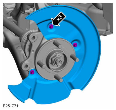
Removal and Installation - Brake Disc Shield
Removal
NOTE: Removal steps in this procedure may contain installation details.
Remove the brake disc.Refer to: Brake Disc (206-03 Front Disc Brake, Removal and Installation).
Remove the bolts and brake disc.
Torque: 80 lb.in (9 Nm)