Ford Ecosport: Passive Anti-Theft System (PATS) - Vehicles With: Keyless Entry and Push Button Start / Diagnosis and Testing - Passive Anti-Theft System (PATS)
DTC Chart: BCM
Diagnostics in this manual assume a certain skill level and knowledge of Ford-specific diagnostic practices.
REFER to: Diagnostic Methods (100-00 General Information, Description and Operation).
| DTC | Description | Action |
|---|---|---|
| B10C6:01 | Exterior Trunk Antenna: General Electrical Failure | GO to Pinpoint Test A |
| B10C8:01 | Interior Centre Antenna: General Electrical Failure | GO to Pinpoint Test A |
| B10C9:01 | Interior Front Antenna: General Electrical Failure | GO to Pinpoint Test A |
| B10D7:05 | PATS Key: System Programming Failure |
DIAGNOSE all other Diagnostic Trouble codes
(DTCs) first. If no other Diagnostic Trouble codes (DTCs) are present,
PROGRAM the suspect passive key again. If key programming fails, REPLACE
the suspect passive key. PROGRAM the new passive key. REFER to: Anti-Theft Key Programming - Scan Tool (419-01C Passive Anti-Theft System (PATS) - Vehicles With: Keyless Entry and Push Button Start, General Procedures). |
| B10D7:55 | PATS Key: Not Configured | The Configurable Engine Immobilizer (CEI) was not completed during the PMI procedure. PERFORM the Configurable Engine Immobilizer (CEI) as part of the PMI procedure. |
| B10D8:00 | PATS Key Less Than Minimum Programmed: No Sub Type Information |
Less than 2 keys are programmed (minimum of 2
keys must be programmed). PROGRAM the customer's second key. REFER to: Anti-Theft Key Programming - Scan Tool (419-01C Passive Anti-Theft System (PATS) - Vehicles With: Keyless Entry and Push Button Start, General Procedures). |
| B10DA:51 | PATS Target Identifier: Not Programmed |
There is no PCM ID stored in the BCM
memory. DIAGNOSE all other Diagnostic Trouble Codes (DTCs) first. If
no other Diagnostic Trouble Codes (DTCs) are present, PERFORM the module
initialization. REFER to: Anti-Theft Key Programming - Scan Tool (419-01C Passive Anti-Theft System (PATS) - Vehicles With: Keyless Entry and Push Button Start, General Procedures). |
| All other Diagnostic Trouble Codes (DTCs) | - |
REFER to: Body Control Module (BCM) (419-10 Multifunction Electronic Modules, Diagnosis and Testing). |
DTC Chart: PCM
Diagnostics in this manual assume a certain skill level and knowledge of Ford-specific diagnostic practices.
REFER to: Diagnostic Methods (100-00 General Information, Description and Operation).
| DTC | Description | Action |
|---|---|---|
| P161A | Incorrect Response from Immobilizer Control Module |
The BCM ID received by the PCM does not match the ID stored in the PCM memory. PERFORM a parameter reset. REFER to: Anti-Theft Key Programming - Scan Tool (419-01C Passive Anti-Theft System (PATS) - Vehicles With: Keyless Entry and Push Button Start, General Procedures). |
| All other Diagnostic Trouble Codes (DTCs) | - | REFER to the PCM DTC Chart in the appropriate 303-14 section. |
Symptom Chart
Symptom Chart: PATS
Diagnostics in this manual assume a certain skill level and knowledge of Ford-specific diagnostic practices.
REFER to: Diagnostic Methods (100-00 General Information, Description and Operation).
| Condition | Possible Sources | Actions |
|---|---|---|
| No Key Detected displays in the IPC message center | Refer to the Pinpoint Test | GO to Pinpoint Test A |
| The vehicle does not start with the passive key in certain areas within the vehicle but starts using the passive key backup location | Refer to the Pinpoint Test | GO to Pinpoint Test A |
| Unable to program keys | Refer to the Pinpoint Test | GO to Pinpoint Test A |
| Unable to turn the ignition on | Refer to the Pinpoint Test | GO to Pinpoint Test B |
Pinpoint Tests
|
Refer to Wiring Diagrams Cell 117 for schematic and connector information. Normal Operation and Fault Conditions
REFER to: Passive Anti-Theft System (PATS) - System Operation and
Component Description (419-01C Passive Anti-Theft System (PATS) -
Vehicles With: Keyless Entry and Push Button Start, Description and
Operation). The PATS does not disable an already running vehicle. DTC Fault Trigger Conditions
Possible Sources
NOTE: If unable to program new keys, follow the diagnostics for DTC B10C8:01. |
|||||||||||||||||||||||||||||||
| A1 CHECK FOR BCM (BODY CONTROL MODULE) ANTENNA DIAGNOSTIC TROUBLE CODES (DTCS) | |||||||||||||||||||||||||||||||
Is BCM DTC B10C6:01, B10C7:01, or B10C8:01 present?
|
|||||||||||||||||||||||||||||||
| A2 CHECK THE RKE (REMOTE KEYLESS ENTRY) TRANSMITTER OPERATION | |||||||||||||||||||||||||||||||
Do the doors lock and unlock?
|
|||||||||||||||||||||||||||||||
| A3 CHECK THE PASSIVE KEY LOCATION | |||||||||||||||||||||||||||||||
Does the vehicle start?
|
|||||||||||||||||||||||||||||||
| A4 CHECK FOR ENVIRONMENTAL INTERFERENCE | |||||||||||||||||||||||||||||||
Does the vehicle start?
|
|||||||||||||||||||||||||||||||
| A5 CHECK THE SUSPECT ANTENNA CIRCUITS FOR A SHORT TO VOLTAGE | |||||||||||||||||||||||||||||||
Is any voltage present?
|
|||||||||||||||||||||||||||||||
| A6 CHECK THE SUSPECT ANTENNA CIRCUITS FOR A SHORT TO GROUND | |||||||||||||||||||||||||||||||
Are the resistances greater than 10,000 ohms?
|
|||||||||||||||||||||||||||||||
| A7 CHECK THE SUSPECT ANTENNA CIRCUITS FOR AN OPEN | |||||||||||||||||||||||||||||||
Are the resistances less than 3 ohms?
|
|||||||||||||||||||||||||||||||
| A8 CHECK THE RESISTANCE OF THE SUSPECT ANTENNA | |||||||||||||||||||||||||||||||
|
NOTE: For a concern with key programming or if unable to start the vehicle with the passive key in the backup starting location, follow the diagnostics for the PATS front/center antenna.
Is the resistance between 1 and 3 ohms?
|
|||||||||||||||||||||||||||||||
| A9 CHECK FOR CORRECT BCM (BODY CONTROL MODULE) OPERATION | |||||||||||||||||||||||||||||||
Is the concern still present?
|


|
Normal Operation and Fault Conditions
REFER to: Passive Anti-Theft System (PATS) - System Operation and
Component Description (419-01C Passive Anti-Theft System (PATS) -
Vehicles With: Keyless Entry and Push Button Start, Description and
Operation). Possible Sources
|
||||
| B1 CHECK VEHICLE BATTERY | ||||
Is the battery OK?
|
||||
| B2 CHECK FOR THE NO KEY DETECTED MESSAGE | ||||
Is the No Key Detected message displayed in the IPC message center?
|
||||
| B3 CHECK FOR IGNITION ON MODE | ||||
Does the ignition mode indicator flash on and off continuously?
|
||||
| B4 CHECK FOR BCM (BODY CONTROL MODULE) AND PCM (POWERTRAIN CONTROL MODULE) DIAGNOSTIC TROUBLE CODES (DTCS) | ||||
Are any BCM or PCM Diagnostic Trouble Codes (DTCs) present?
|

 General Procedures - Anti-Theft Key Programming - Scan Tool
Programming
NOTE:
A passive key with a depleted battery(ies) only starts the vehicle when
in the backup starting location. The RKE functionality remains
inoperative until the key battery(ies) is replaced...
Other information:
Ford Ecosport 2014-2025 Service and Repair Manual: Description and Operation - Communications Network - Overview
Overview Multiplexing is a method of sending 2 or more signals simultaneously over a single circuit. Multiplexing allows 2 or more electronic modules (nodes) to communicate over a twisted wire pair [data (+) and data (-)] network. The information or messages that can be communicated on these wires consists of commands, status or data...
Ford Ecosport 2014-2025 Service and Repair Manual: Removal and Installation - Instrument Panel Center Speaker
Special Tool(s) / General Equipment Interior Trim Remover Removal NOTE: Removal steps in this procedure may contain installation details. NOTE: 8 inch display is shown, all other displays are similar. Release the clips and remove the screw cover trim panel...
Categories
- Manuals Home
- 2nd Gen Ford Ecosport Service Manual (2014 - 2025)
- Diagnosis and Testing - Body Control Module (BCM)
- Climate Control System - General Information
- Automatic Transmission - 6-Speed Automatic Transmission – 6F35
- Diagnosis and Testing - Powertrain Control Module (PCM) Input and Output Controls
- Removal and Installation - Rear Bumper
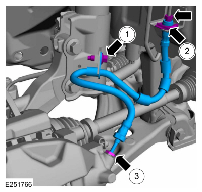
Removal and Installation - Front Brake Flexible Hose
Removal
Remove the wheel and tire.Refer to: Wheel and Tire (204-04A Wheels and Tires, Removal and Installation).
Remove the brake flexible hose bracket bolt.
Disconnect the brake tube fitting and remove the brake hose clip.
Loosen the brake hose fitting and remove the brake flexible hose.