Ford Ecosport: Exhaust System - 2.0L Duratec-HE (129kW/175PS) / Diagnosis and Testing - Catalyst System
Diagnostic Trouble Code (DTC) Chart
Diagnostics in this manual assume a certain skill level and knowledge of Ford-specific diagnostic practices.
REFER to: Diagnostic Methods (100-00 General Information, Description and Operation).
| Module | DTC | Description | Action |
|---|---|---|---|
| PCM | P0420:00 | Catalyst System Efficiency Below Threshold (Bank 1): No Sub Type Information | GO to Pinpoint Test HF |
Global Customer Symptom Code (GCSC) Chart
Diagnostics in this manual assume a certain skill level and knowledge of Ford-specific diagnostic practices.
REFER to: Diagnostic Methods (100-00 General Information, Description and Operation).
| Symptom | Action |
|---|---|
| Start/Run/Move > Running > Failed Emissions Testing > Catalyst | GO to Pinpoint Test EM |
| Start/Run/Move > Odor > Chemical > Always | GO to Pinpoint Test HF |
Pinpoint Tests
 PINPOINT TEST EM: EMISSION COMPLIANCE
 Introduction Introduction
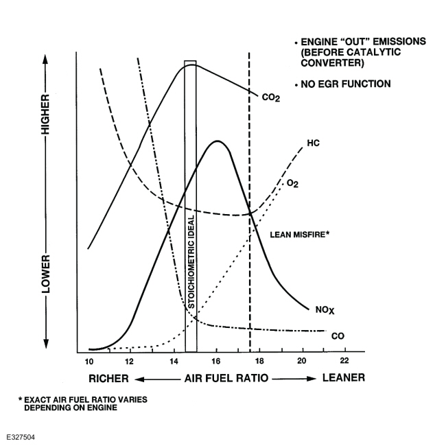
NOTE: Canada and some states or metropolitan areas in the United States require periodic emission, or inspection/maintenance tests. All Ford products are designed to pass these tests. If a Ford product fails the test, the most likely causes are:
Normal Operation and Fault Conditions If any new emission components are installed, carry out the following steps before repeating the inspection/maintenance test procedure:

Verifying an excessive grams per mile (gpm) indication using a parts per million (ppm) reading. For excessive vehicle gas readings, compare the actual gpm reading to the gas cutpoint level needed to pass testing. This gives an indication of how much the ppm reading has to be reduced (if the actual reading is twice the cutpoint, the baseline reading has to be cut in half or more). Example:
Possible Sources
|
 PINPOINT TEST HF: CATALYST EFFICIENCY MONITOR AND EXHAUST SYSTEMS
 Introduction Introduction
Normal Operation and Fault Conditions Refer to the DTC Fault Trigger Conditions. DTC Fault Trigger Conditions
Possible Sources
|
 Description and Operation - Exhaust System - System Operation and Component Description
System Operation
Catalyst And Exhaust Systems
The
catalytic converter and exhaust systems work together to control the
release of harmful engine exhaust emissions into the atmosphere...
 Diagnosis and Testing - Exhaust System
Symptom Chart(s)
Symptom Chart: Symptom Chart - Exhaust System
Verify
the customer concern. Inspect the components of the exhaust system for
obvious signs of damage or other mechanical concerns using the following
chart...
Other information:
Ford Ecosport 2014-2026 Service and Repair Manual: Description and Operation - Torque Converter Clutch (TCC)
TCC Hydraulic Circuits 1 Inspect the pump to transmission case hydraulic passages and seals. 2 Inspect the transmission case to main control hydraulic passages. 3 Inspect the main control hydraulic passages...
Ford Ecosport 2014-2026 Service and Repair Manual: Removal and Installation - Axle Assembly
Removal NOTE: Removal steps in this procedure may contain installation details. Remove the rear subframe - AWD. Refer to: Rear Subframe - AWD (502-00 Uni-Body, Subframe and Mounting System, Removal and Installation). Remove the bolts and the RDU front mounting brackets...

 PINPOINT TEST EM: EMISSION COMPLIANCE

 Introduction
