Ford Ecosport: Multifunction Electronic Modules / Description and Operation - Module Controlled Functions - Component Location
Ford Ecosport 2014-2025 Service and Repair Manual / Electronic Feature Group / Multifunction Electronic Modules / Description and Operation - Module Controlled Functions - Component Location
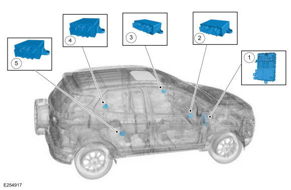
| Item | Description |
|---|---|
| 1 | BCM |
| 2 | PDM (if equipped) |
| 3 | DDM (if equipped) |
| 4 | RDM - LH (if equipped) |
| 5 | RDM - RH (if equipped) |

 Description and Operation - Module Controlled Functions - System Operation and Component Description
System Operation
BCM
The BCM controls various systems by monitoring inputs from switches,
sensors and network messages from other modules on the HS-CAN and from
the GWM ...
Other information:
Ford Ecosport 2014-2025 Service and Repair Manual: Description and Operation - Instrument Panel Cluster (IPC) - System Operation and Component Description
System Operation System Diagram - Gauges Item Description 1 IPC 2 GWM 3 PCM 4 Fuel level sender 5 Tachometer 6 Speedometer 7 Temperature 8 Fuel 9 AWD Network Message Chart - Gauges Module Network Input Messages -..
Ford Ecosport 2014-2025 Service and Repair Manual: Diagnosis and Testing - Stoplamps
DTC Chart: BCM Diagnostics in this manual assume a certain skill level and knowledge of Ford-specific diagnostic practices. REFER to: Diagnostic Methods (100-00 General Information, Description and Operation). BCM DTC Chart DTC Description Action B1115:11 High Mounted ..
Categories
- Manuals Home
- 2nd Gen Ford Ecosport Service Manual (2014 - 2025)
- Diagnosis and Testing - Evaporative Emissions
- Diagnosis and Testing - Powertrain Control Module (PCM) Input and Output Controls
- Removal and Installation - Front Seat
- Description and Operation - Jacking and Lifting - Overview
- Diagnosis and Testing - Body Control Module (BCM)
Removal and Installation - Rear Halfshaft Seal
Special Tool(s) / General Equipment
 205-153
(T80T-4000-W)
205-153
(T80T-4000-W)
Handle
 205-990
Installer, Axle Seal
TKIT-2012A-FL
TKIT-2012A-ROW
Copyright © 2025 www.foecosport2.com