Ford Ecosport: Anti-Lock Brake System (ABS) and Stability Control / Description and Operation - Anti-Lock Brake System (ABS) - System Operation and Component Description
System Operation
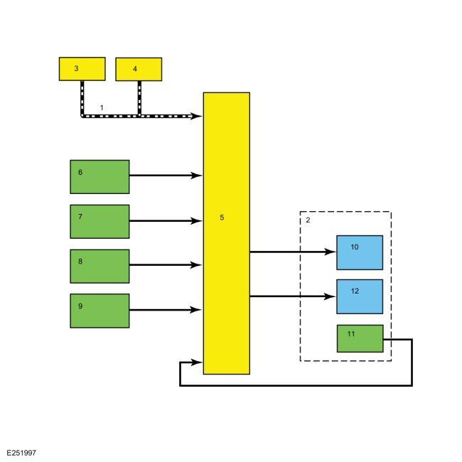
System Diagram

| Item | Description |
|---|---|
| 1 | HS-CAN |
| 2 | HCU |
| 3 | PCM |
| 4 | IPC |
| 5 | ABS module |
| 6 | LH front wheel speed sensor |
| 7 | RH front wheel speed sensor |
| 8 | LH rear wheel speed sensor |
| 9 | RH rear wheel speed sensor |
| 10 | Hydraulic pump motor |
| 11 | Hydraulic pressure sensor |
| 12 | Hydraulic valve solenoids |
Network Message Chart
Module Network Input Messages - ABS Module
| Broadcast Message | Originating Module | Message Purpose |
|---|---|---|
| Brake on-off switch | PCM | This message informs the ABS module the driver has pressed the brake pedal. This message is also used by the ABS module to check the brake pressure sensor located inside the HCU . |
| Clutch pedal switch | IPC (manual transmission only) | This message informs the ABS module the driver has pressed the clutch pedal. |
| Engine speed | PCM | This message informs the ABS module of the current engine speed in RPM . |
| Engine status | PCM | This message informs the ABS module of the current status of the engine; off, ready, cranking, running, stalled, after-run, or shutdown. |
| Ignition status | IPC | This message informs the ABS module of the current ignition status; off, accessory, run, start, unknown or invalid. |
| Parking brake status | IPC | This message informs the ABS module of the current parking brake status: applied or released. |
| Power mode | IPC | This message provides the ABS module with the current ignition status; key out, key recently out, key approved, post accessory, accessory, post ignition, ignition ON, engine running, engine running standby, engine running starting in progress and engine cranking. |
| Selector lever (PRNDL) status | PCM | This message informs the ABS module of the current driver selected gear. |
| Vehicle configuration data | IPC | This message provides the ABS module with the current optional and configured items such as, tire size, axle ratio, manual or automatic transaxle, keyless entry, and VIN . |
Anti-Lock Brake System (ABS) Function
The ABS module continuously monitors brake pedal input and the rotational speed of each wheel. The ABS module receives the brake pedal input from the PCM over the HS-CAN , while wheel speed information is retrieved by the ABS module using 4 wheel speed sensors. When the ABS module detects an impending wheel lock during a braking event, it modulates brake pressure to the appropriate brake caliper(s) by opening and closing the appropriate solenoid valves inside the HCU while the hydraulic pump motor is activated. Once the affected wheel(s) return to the desired speed, the ABS module returns the solenoid valves in the HCU to their normal position.
The ABS module has 2 self-test options, one uses the scan tool and the other is carried out when the ABS module is initialized (ignition ON). During either self-test the ABS module carries out a preliminary electrical check of the system sensors and activates the hydraulic pump motor for approximately one-half second. During this time, a buzzing or humming noise may be heard and a vibration may be felt in the brake pedal and is a normal condition. During the module initialized self-test, the pump motor check is carried out at approximately 20 km/h (12 mph). Any malfunction detected in the system causes the module to set a DTC , disables the ABS and send a message over the HS-CAN to the IPC to illuminate the ABS warning indicator.
Electronic Brake Force Distribution (EBD)
The ABS module incorporates a strategy called EBD . The EBD strategy uses the HCU as an electronic proportioning valve. On initial application of the brake pedal, full pressure is applied to the rear brakes. The ABS module uses wheel speed sensor input to calculate an estimated rate of deceleration. Once vehicle deceleration exceeds a certain threshold, the ABS module closes the appropriate solenoid valves in the HCU to hold the rear brake pressure constant while allowing the front brake pressure to build. This creates a balanced braking condition between the front and rear wheels and minimizes the chance of rear wheel lockup during hard braking. As the vehicle decelerates, the valves open to increase the rear brake pressure in proportion to the front brake pressure.
If 2 or more wheel speed sensor Diagnostic Trouble Codes (DTCs) set in the ABS module or a HCU DTC sets in the ABS module, EBD is disabled. When EBD is disabled, the ABS warning indicator, the red brake warning indicator and the stability-traction control indicator (sliding car icon) illuminate.
Vacuum On Demand System
Vehicles equipped with a 2.0L engine supply vacuum to the brake booster through the use of a valve solenoid and an aspirator in the brake booster vacuum tube. When the ABS module detects a low vacuum condition in the brake booster, a message is sent to the PCM requesting additional vacuum. The PCM responds by opening the valve solenoid which allows the engine to draw air from the brake booster, increasing vacuum in the booster. Once the vacuum in the booster has reached the required level, the ABS module stops sending the message and the PCM closes the valve solenoid.
Component Description
Anti-Lock Brake System (ABS) Module
The ABS module is attached directly to the HCU and is the ECU for the ABS . The ABS module monitors all sensor inputs and all HS-CAN messages relating to anti-lock brake control, then directly controls the solenoid valves and the hydraulic pump motor in the HCU .
The ABS module and HCU are connected together but are serviced
separately. When a new ABS is installed, the module must be programmed
with the vehicle information.
Refer to: Communications Network -
System Operation and Component Description (418-00 Module Communications
Network, Description and Operation).
Hydraulic Control Unit (HCU)
The HCU contains the solenoid valves, the hydraulic pump motor and the pressure sensor used by the ABS module for ABS operation. The ABS module and HCU are connected together but are serviced separately.
Wheel Speed Sensor
The wheel speed sensors are active (magneto resistive) sensors operating on the Hall-effect principle to generate a square wave signal proportional to the rotational speed of the wheel. Because these are active sensors, receiving voltage from the ABS module and then sending a varying voltage back to the module, they are able to detect much lower rotational speeds than passive (magnetic inductive) sensors. Each wheel speed sensor is connected to the ABS module by 2 circuits which are used for both sensor power and sensor signal return.
Wheel Speed Sensor Encoders
The wheel speed sensor encoders are several magnets arranged in a circle around one side of the wheel bearing in alternating poles. As the wheel bearing rotates the wheel speed sensor is exposed to alternating north-south magnetic fields. The encoder is part of the wheel bearing and is serviced with the bearing.
 Description and Operation - Anti-Lock Brake System (ABS) - Overview
Overview
The ABS system is comprised of the following subsystems which assist
the driver in maintaining control of the vehicle during braking:
ABS
EBD
The ABS helps maintain steering control by preventing the wheels
from locking up during hard braking...
 Description and Operation - Anti-Lock Brake System (ABS) and Stability Control - Component Location
Item
Description
1
ABS module and HCU assembly
2
Rear wheel speed sensor (2 required)
3
RCM
4
Front wheel speed sensor (2 required)
..
Other information:
Ford Ecosport 2014-2024 Service and Repair Manual: Description and Operation - About this Manual
Introduction WARNING: Before beginning any service procedure in this manual, refer to health and safety warnings in section 100-00 General Information. Failure to follow this instruction may result in serious personal injury. For additional information, refer to: Health and Safety Precautions (100-00 General Information, Description and Operation). This manual ..
Ford Ecosport 2014-2024 Service and Repair Manual: Removal and Installation - Front Stabilizer Bar Link
Removal NOTICE: Suspension fasteners are critical parts that affect the performance of vital components and systems. Failure of these fasteners may result in major service expense. Use the same or equivalent parts if replacement is necessary. Do not use a replacement part of lesser quality or substitute design. Tighten fasteners as specified. NOTE: Removal steps in this proc..
Categories
- Manuals Home
- 2nd Gen Ford Ecosport Service Manual (2014 - 2024)
- Removal and Installation - Starter Motor
- Removal and Installation - Fuel Filler Door Assembly
- Body and Paint
- Engine
- Removal and Installation - Roof Rail
Removal and Installation - Rear Halfshaft Seal
Special Tool(s) / General Equipment
 205-153
(T80T-4000-W)
205-153
(T80T-4000-W)
Handle
 205-990
Installer, Axle Seal
TKIT-2012A-FL
TKIT-2012A-ROW