Ford Ecosport: Anti-Lock Brake System (ABS) and Stability Control / Description and Operation - Anti-Lock Brake System (ABS) and Stability Control - Overview
Overview
The ABS and stability control systems are comprised of the following subsystems which assist the driver in maintaining control of the vehicle:
- ABS
- EBA
- EBD
- ESC
- Hill start assist
- Traction control
The ABS helps maintain steering control by preventing the wheels from locking up during hard braking. The ABS also includes a brake assist function that provides maximum brake system pressure during a severe braking event.
The EBA system uses the hydraulic pump motor and HCU to provide additional braking assist during a severe braking event.
The EBD system helps maintain vehicle control by keeping a balanced braking condition between the front and rear wheels.
The ESC system helps prevent skids or lateral slides by activating portions of the ABS .
The hill start assist system is designed to assist the driver during hill-starts. Using the ABS , the hill start assist system holds the vehicle on an incline for a short time, allowing the driver to release the brake pedal and press the accelerator pedal without needing to use the parking brake.
The traction control system helps prevent loss of traction by reducing drive-wheel spin during acceleration.
Some noise from the system and pulsations in the brake pedal are normal conditions during most ABS and stability control events. Longer than normal brake pedal travel may also be experienced immediately following an ABS or stability control activation.
 Description and Operation - Anti-Lock Brake System (ABS) and Stability Control - Component Location
..
 Description and Operation - Anti-Lock Brake System (ABS) and Stability Control - System Operation and Component Description
System Operation
System Diagram
Item
Description
1
HCU
2
PCM
3
IPC
4
ABS module
5
RCM
6
PSCM
7
BCM
8
LH Front wheel speed sensor
9
RH Front wheel speed sensor
10
LH Rear wheel speed sensor
11
LH Rear whe..
Other information:
Ford Ecosport 2014-2024 Service and Repair Manual: Removal and Installation - Front Bumper Cover
Removal NOTE: Removal steps in this procedure may contain installation details. Remove the fender splash shield. Refer to: Fender Splash Shield (501-02 Front End Body Panels, Removal and Installation). On both sides. Disconnect the headlamp electrical connector and detach the wiring harness retainer. Remove the screws. Tor..
Ford Ecosport 2014-2024 Service and Repair Manual: Removal and Installation - Wheel Bearing and Wheel Hub - Vehicles With: Rear Disc Brakes
Special Tool(s) / General Equipment 204-180 (T93P-5493-A) Remover/Installer, BushingTKIT-1993-FLMTKIT-1993-LMTKIT-1993-FM 205-014 (T60K-4616-A) Installer, Drive Pinion Bearing Cup 205-090 (T75L-1165-B) Plate, Bearing/Oil Seal 205-140 (T80T-4000-F) Installer, Drive Pinion Bearing Cup 205-153 (T80T-4000-W) Handle ..
Categories
- Manuals Home
- 2nd Gen Ford Ecosport Service Manual (2014 - 2024)
- Description and Operation - Jacking and Lifting - Overview
- General Procedures - Transmission Fluid Level Check
- Removal and Installation - Body Control Module (BCM)
- Automatic Transmission - 6-Speed Automatic Transmission – 6F35
- Diagnosis and Testing - Body Control Module (BCM)
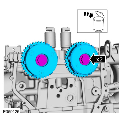
Removal and Installation - Variable Camshaft Timing (VCT) Unit
Removal
NOTICE: During engine repair procedures, cleanliness is extremely important. Any foreign material, including any material created while cleaning gasket surfaces, that enters the oil passages, coolant passages or the oil pan can cause engine failure.
Remove the timing chain.Refer to: Timing Chain (303-01C Engine - 2.0L Duratec-HE (129kW/175PS), Removal and Installation).
Remove the bolts and VCT units.
Discard the bolts.